Audi Q7: Connectors
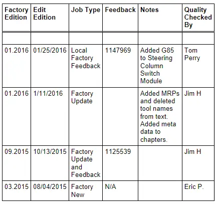
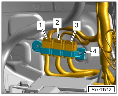
Component Location Overview - Connectors
1 - Left Front Door Cut-Off Connector
- Disconnecting. Refer to → Chapter "Front Door Cut-Off Connector, Disconnecting".
2 - Right Front Door Cut-Off Connector
- Disconnecting. Refer to → Chapter "Front Door Cut-Off Connector, Disconnecting".
3 - Right Bulkhead Connector Station
- Removing and installing. Refer to → Chapter "Right Bulkhead Connector Station, Removing and Installing".
4 - Right Rear Door Cut-Off Connector
- Disconnecting. Refer to → Chapter "Rear Door Cut-Off Connector, Disconnecting".
5 - Left Rear Door Cut-Off Connector
- Disconnecting. Refer to → Chapter "Rear Door Cut-Off Connector, Disconnecting".
6 - Fuse Panel B -SB- Connector Station
- Removing and installing. Refer to → Chapter "Fuse Panel B -SB-, Removing and Installing".
Door Cut-Off Connector, Disconnecting
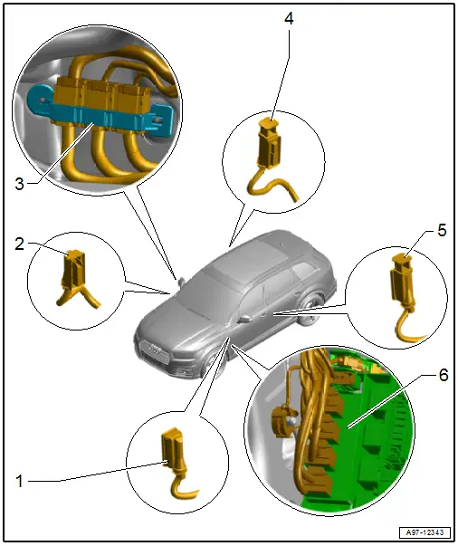
Front Door Cut-Off Connector, Disconnecting
Procedure
- Open the door.
- Release the connector safety catch in the direction of -arrow A- and remove the door cut-off connector -1- outward in direction of -arrow B-.
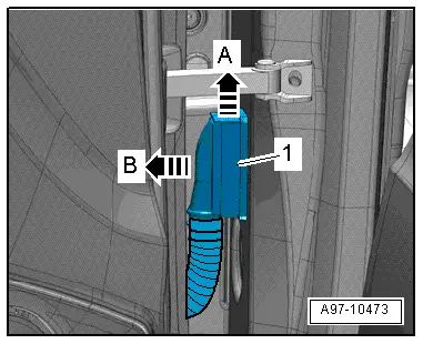
Rear Door Cut-Off Connector, Disconnecting
Procedure
- Front door open.
- Remove the retainer in the direction of -arrow A-.
- Pull the door cut-off connector -1- as far as possible toward the outside in direction of -arrow B-.

- Install the retainer -3-.
- Swivel the door cut-off connector -1- forward in direction of -arrow- and disconnect the connector -2-.
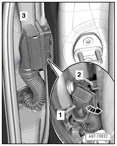
Right Bulkhead Connector Station, Removing and Installing
Removing
- Remove the carpet on the front passenger side. Refer to → Body Interior; Rep. Gr.70; Vehicle Interior Trim Panels; Carpet, Removing and Installing.
- Turn off the ignition and disconnect the ground cable from the battery. Refer to → Chapter "Battery, Disconnecting and Connecting".
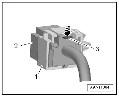
- Disconnect the connectors -1 and 2- by sliding the retainer toward the rear and pressing the release down.
- Remove the connector station -3- from the threaded pin.
- Release the retainer -3--arrow- and push the connector terminal -2- out of the bracket -1-.
Installing
Install in the reverse order of removal while noting the following:
- Connect the battery. Required actions.
Special Tools
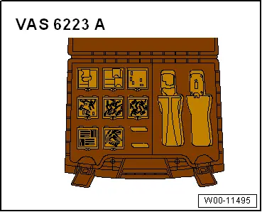
Special tools and workshop equipment required
- Fiber-Optic Repair Set - Connector Protective Caps -VAS6223/9- from Fiber-Optic Repair Set -VAS6223B-
Revision History
DRUCK NUMBER: A005A011321