Audi Q7: Coolant Pipes
Overview - Coolant Pipes
 Note
Note
The arrows on the coolant pipes and ends of coolant hoses must align.
Coolant Pipe on the Engine
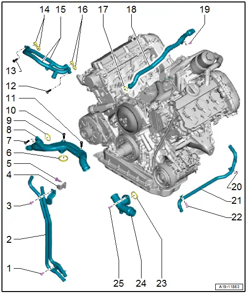
1 - Bolt
- 9 Nm
2 - Left Front Coolant Pipes
- Removing and installing. Refer to → Chapter "Front Left Coolant Pipes, Removing and Installing".
3 - Bolt
- 9 Nm
4 - Bracket
5 - Bolt
- 22 Nm
6 - Seal
- Replace after removing
7 - Bolt
- 9 Nm
8 - Right Front Coolant Pipe
- Removing and installing. Refer to → Chapter "Right Front Coolant Pipe, Removing and Installing".
9 - Seal
- Replace after removing
10 - Bolt
- 9 Nm
11 - Bolt
- 9 Nm
12 - Bolt
- 5 Nm
13 - Bolt
- 5 Nm
14 - Seals
- Replace after removing
15 - Coolant Pipes on the Compressor
- Removing and installing. Refer to → Chapter "Supercharger Coolant Pipes, Removing and Installing".
16 - Seals
- Replace after removing
17 - O-Ring
- Replace after removing
18 - Upper Coolant Pipe
- Removing and installing. Refer to → Chapter "Upper Coolant Pipe, Removing and Installing".
19 - Bolt
- 9 Nm
20 - Bolt
- 9 Nm
21 - Left Coolant Pipe
- Removing and installing. Refer to → Chapter "Left Coolant Pipe, Removing and Installing".
22 - Bolt
- 9 Nm
23 - Gasket
- Replace after removing
24 - Left Front Coolant Pipe
- Removing and installing. Refer to → Chapter "Front Left Coolant Pipe, Removing and Installing".
25 - Bolt
- 9 Nm
Coolant Pipe on the Transmission
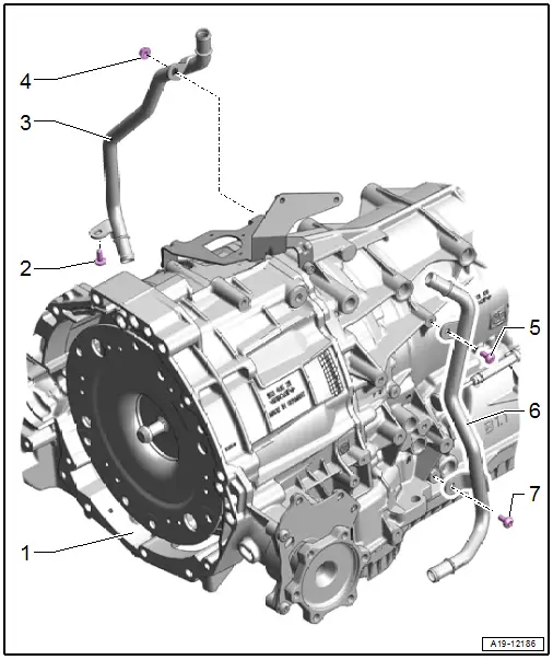
1 - Transmission
2 - Bolt
- 8 Nm
3 - Right Coolant Pipe on the Transmission
- Removing and installing. Refer to → Chapter "Right Coolant Pipe on Transmission, Removing and Installing".
4 - Nut
- 8 Nm
5 - Bolt
- 8 Nm
6 - Left Coolant Pipe on Transmission
- Removing and installing. Refer to → Chapter "Left Coolant Pipe on Transmission, Removing and Installing".
7 - Bolt
- 8 Nm

