Audi Q7: Engine Control Module
Overview - Engine Control Module
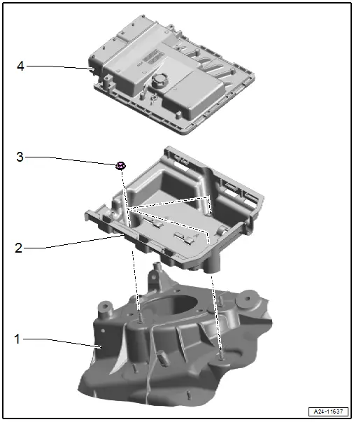
1 - Suspension Strut Tower
2 - Mount
- For the Engine Control Module -J623-
3 - Nut
- 9 Nm
4 - Engine Control Module -J623-
- Removing and installing. Refer to → Chapter "Engine Control Module -J623-, Removing and Installing".
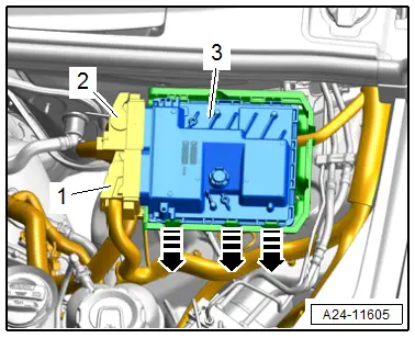
Engine Control Module -J623-, Removing and Installing
Removing
- Switch off the ignition.
- Disconnect the connectors -1 and 2-.
- Release the catches in direction of -arrows- and remove the Engine Control Module -J623-.
Installing
Install in reverse order of removal and note the following:
- If the Engine Control Module -J623- was replaced. Refer to Vehicle Diagnostic Tester, 01 - Replacing control module.
- If the Engine Control Module -J623- was replaced. Refer to Vehicle Diagnostic Tester, 01 - Adaptation Values, Adapting after Component Replacement.
- Start the selected program and follow the instructions in the display of the Vehicle Diagnostic Tester.
Tightening Specifications
- Refer to → Chapter "Overview - Engine Control Module"
Special Tools
Special tools and workshop equipment required
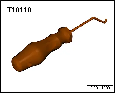
- Elbow Assembly Tool -T10118-
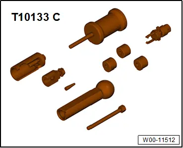
- Injector/Combustion Chamber Seal Tool Set -T10133C-
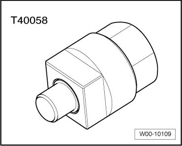
- Crankshaft Socket -T40058-
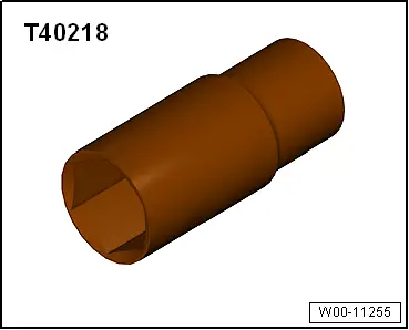
- Socket - 27mm -T40218- or 27 mm socket, commercially available
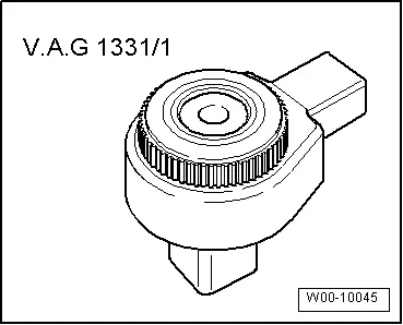
- Torque Wrench 1331 Insert - Reversible Ratchet -VAG1331/1-
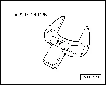
- Torque Wrench 1331 Insert - Open Jaw - 17mm -VAG1331/6-
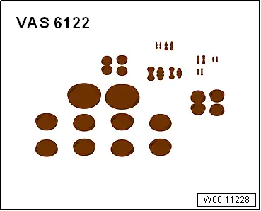
- Engine Bung Set -VAS6122-
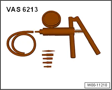
- Hand Vacuum Pump -VAS6213-
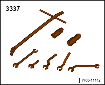
- Ring Wrench 7-Piece Set -3337-
- Torque Wrench 1331 5-50Nm -VAG1331-
- Torque Wrench 1331 Insert - Ring Wrench - 11mm & 17mm -VAG1331/2-
- Torque Wrench 1331 Insert - Open Ring Wrench - 14mm -VAG1331/8-