Audi Q7: Engine Cover
Engine Cover, Removing and Installing
Removing
- Remove the air filter housing. Refer to → Chapter "Air Filter Housing, Removing and Installing".
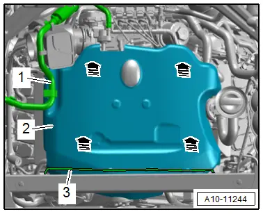
- Free up the vacuum hoses -1 and 3-.
- Carefully pull the engine cover -2- off of the retaining pins one after the other in direction of -arrows-. Do not pull sharply on the engine cover or pull it to one side.
Installing
- To prevent damage to the engine cover, do not hit it with a fist or a tool.
- Press the engine cover into the rubber grommets on the left side first, then into the ones on the right side.
- Install the air filter housing. Refer to → Chapter "Air Filter Housing, Removing and Installing".
Special Tools
Special tools and workshop equipment required
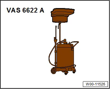
- Used Oil Collection and Extraction Unit -SMN372500-
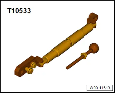
- Engine Support -T10533-
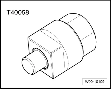
- Crankshaft Socket -T40058-
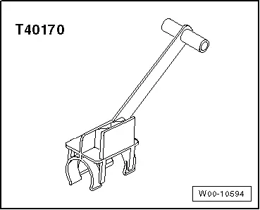
- Clutch Module Transportation Lock -T40170-
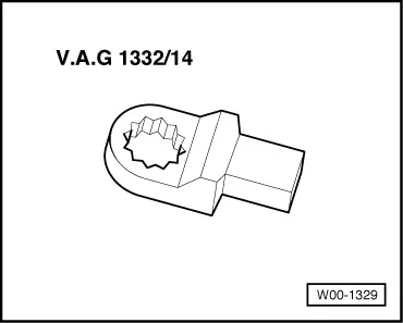
- Torque Wrench 1332 Insert - Ring Wrench - 16mm -VAG1332/14-
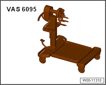
- Engine and Gearbox Bracket -VAS6095A-
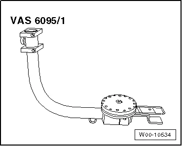
- Engine/Transmission Holder - Universal Mounting -VAS6095/1- and Engine/Transmission Holder - V6 FSI Bracket -VAS6095/1-5-
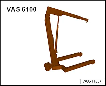
- Shop Crane -VAS6100-
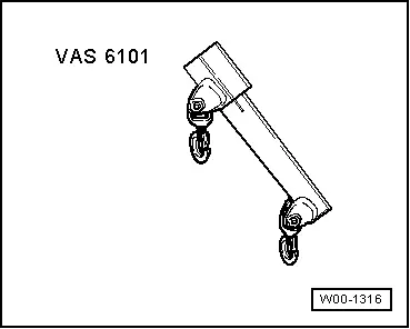
- Lift Arm Extension -VAS6101-
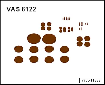
- Engine Bung Set -VAS6122-
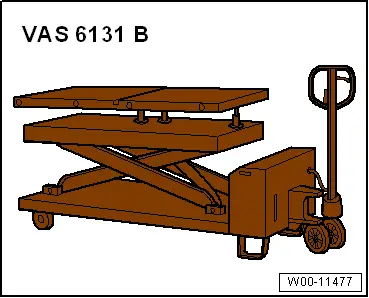
- Scissor Lift Table -VAS6131B-
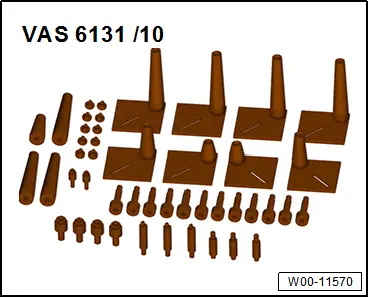
- Scissor Lift Table - Audi Set -VAS6131/10-
- Scissor Lift Table - A8 Set -VAS6131/11-
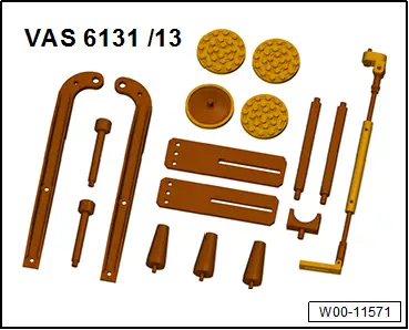
- Scissor Lift Table - Q7 Set -VAS6131/13-
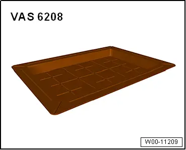
- Coolant Collection System -VAS5014- or Shop Crane - Drip Tray -VAS6208 -
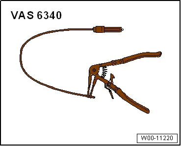
- Hose Clip Pliers -VAS6340-
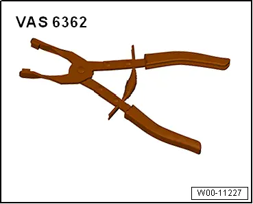
- Hose Clip Pliers -VAS6362-
- Engine Support Bridge -10-222A-

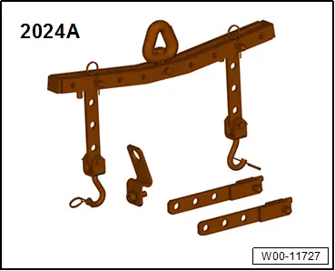
- Engine Sling -2024A-
- Engine Support Bridge - Engine Bracket -10-222A/1-
- Adapters -10-222A/34-