Audi Q7: Final Drive
Overview - Final Drive
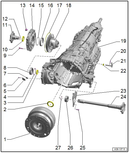
1 - Torque Converter
- Overview. Refer to → Chapter "Overview - Torque Converter".
2 - Seal
- For the torque converter
- Removing and installing. Refer to → Chapter "Torque Converter Seal, Removing and Installing".
3 - Seal
- For the left flange shaft
- Between the final drive and the transmission housing
- Replacing. Refer to → Chapter "Left Seal, Replacing".
4 - Shim
- Behind the taper roller bearing outer race
5 - Bracket
- For the magnet
6 - Bolt
- 6 Nm
7 - Magnet
- Clean if necessary
8 - Taper Roller Bearing Outer Race
9 - Bolt
- There are different versions. Refer to the Parts Catalog for the correct allocation.
- Tightening specification and sequence. Refer to → Fig. "Front Final Drive Cover - Tightening Specifications and Sequence".
10 - Seal
- For the right flange shaft
- Replacing. Refer to → Chapter "Right Seal, Replacing".
11 - Right Flange Shaft
- Removing and installing. Refer to → Chapter "Right Flange Shaft, Removing and Installing".
12 - Circlip
- Replacing
13 - Plug
- For the hole for checking and filling
- For the transmission fluid inside the front final drive
- Tightening specification.
14 - Cover
- For the front final drive
- Pay attention to the alignment sleeves
15 - Shim
- Behind the taper roller bearing outer race
16 - Taper Roller Bearing Outer Race
17 - O-Ring
- On the front final drive cover
- Removing and installing. Refer to → Chapter "O-Ring on Front Final Drive Cover, Removing and Installing".
18 - Differential
19 - Transmission
20 - Spring Pin
- Replace after removing
- Removing and installing. Refer to → Chapter "Selector Shaft Seal, Replacing".
- Installation position. Refer to → Fig. "Spring Pin Installation Position".
21 - Selector Lever
- Removing and installing. Refer to → Chapter "Selector Shaft Seal, Replacing".
22 - Seal
- For the transmission shift lever
- Replacing. Refer to → Chapter "Selector Shaft Seal, Replacing".
23 - Gear Carrier
- Use the clip -item 27- to attach together with the mount -item 26- to the left flange shaft.
- Is identified together as the left flange shaft mounting bracket.
24 - Left Flange Shaft
- Removing and installing. Refer to → Chapter "Left Flange Shaft, Removing and Installing".
25 - Bolt
- 9 Nm +60º
- Replacing
26 - Bearings
- For the left flange shaft
27 - Circlip
- For the left flange shaft bearing
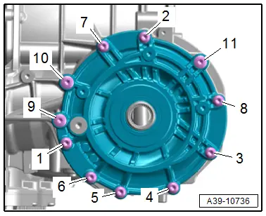
Front Final Drive Cover - Tightening Specifications and Sequence
- Tighten the bolts in the steps in the specified sequence:

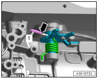
Spring Pin Installation Position
- Drive in the new spring pin -1- with the narrow side -arrow- flush.
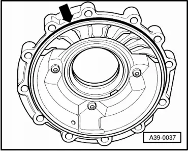
O-Ring on Front Final Drive Cover, Removing and Installing
 Caution
This procedure contains mandatory replaceable parts. Refer to component overview prior to starting procedure.
Mandatory Replacement Parts
- O-ring - Front final drive cover
Procedure
 Note
Note
- General repair instructions. Refer to → Chapter "General Repair Information".
- Guidelines for clean working conditions. Refer to → Chapter "Guidelines for Clean Working Conditions".
- Drain the gear oil from front final drive. Refer to → Chapter "Gear Oil, Draining and Filling".
- Remove the right flange shaft. Refer to → Chapter "Right Flange Shaft, Removing and Installing".
- Remove the bolts from the front final drive cover in the following sequence: -11 to 1-.
- Remove the front final drive cover together with the tapered roller bearing outer race and the shim.
 Note
Note
The shim must be the correct size and must not be replaced by a shim with a different thickness.
- Replace the O-ring -arrow-.
- Insert the differential into the transmission housing.
If the tapered roller bearing outer race and the shim have fallen out of the front final drive cover:
- Lubricate the shim and tapered roller bearing outer race with gear oil and insert them into the front final drive cover as far as the stop.
- Tighten the front final drive cover bolts.
- Install the right flange shaft. Refer to → Chapter "Right Flange Shaft, Removing and Installing".
- Add gear oil to the transmission after repair. Refer to → Chapter "Gear Oil, Draining and Filling".

Tightening Specifications
- → Fig. "Front Final Drive Cover - Tightening Specifications and Sequence"

