Audi Q7: Microphone Unit in Front Roof Module -R164-, Removing and Installing
The Microphone Unit in Front Roof Module -R164- located in the Front Interior Lamp -W1- can be replaced only as a complete unit.
Removing
- Turn off the ignition and all electrical equipment and remove the ignition key.
- Remove the Front Interior Lamp -W1-. Refer to → Electrical Equipment; Rep. Gr.96; Controls; Front Interior Lamp/Reading Lamp, Removing and Installing.
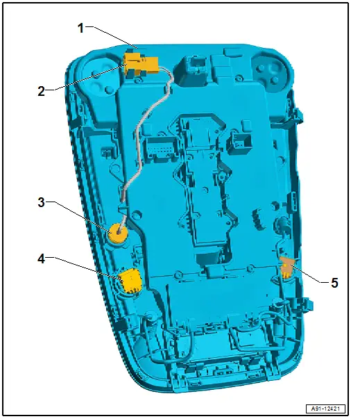
- Unclip the connector -2- from the holder in the Front Interior Lamp -W1--1- and disconnect the connector.
- Pry each microphone -3-, -4- and -5- out of the Front Interior Lamp -W1--1-.
Installing
- Install in reverse order of removal.
Cellular Telephone Amplifier -R86-, Removing and Installing
The Cellular Telephone Amplifier -R86- is behind the right luggage compartment side trim panel.
Removing
- Turn off the ignition and all electrical equipment and remove the ignition key.
- Remove the right luggage compartment side trim panel. Refer to → Body Interior; Rep. Gr.70; Luggage Compartment Trim Panels; Luggage Compartment Side Trim Panel, Removing and Installing.
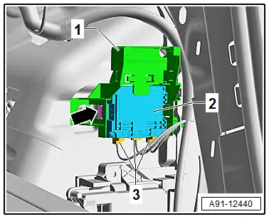
- Release and disconnect the connectors -3- from the Cellular Telephone Amplifier -R86--2-.
- Press the catches -arrow- and remove the Cellular Telephone Amplifier -R86--2- from the bracket -1-.
Installing
- Install in reverse order of removal.
Telephone Baseplate -R126-, Removing and Installing
Telephone Baseplate -R126-, Removing and Installing
The Telephone Baseplate - R126- is located under the front center armrest
Removing
- Turn off the ignition and all electrical equipment and remove the ignition key.
- Remove the Cellular Telephone -R54-.
- Remove the center console. Refer to → Body Interior; Rep. Gr.68; Center Console; Center Console, Removing and Installing.
- Release and disconnect the connectors.
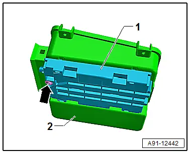
- Remove the bolt -arrow-.
- Remove the Telephone Baseplate -R126--1- from the storage compartment -2-.
Installing
- Install in reverse order of removal.
Tightening Specifications
- Refer to → Chapter "Component Location Overview - Telephone System"
Telephone Baseplate - R126-, Removing and Installing, Wireless Charger
Special tools and workshop equipment required
- Trim Removal Wedge -3409-
The Telephone Baseplate - R126- is located under the front center armrest in the storage compartment.
Removing
- Turn off the ignition and all electrical equipment and remove the ignition key.
- Remove the Cellular Telephone -R54-.
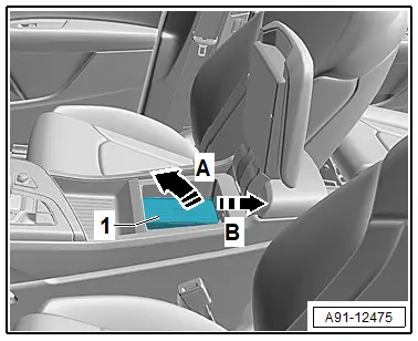
The Telephone Baseplate -R126- is only clipped in the storage compartment.
- Push the Telephone Baseplate -R126--1- with the Trim Removal Wedge -3409- upward in direction of -arrow A-, and then pull it toward the rear in direction of -arrow B- and remove it from the storage compartment.
- Release and disconnect the connectors.
Installing
- Install in reverse order of removal.

