Audi Q7: Chain Drive
Overview - Camshaft Timing Chains
Left Camshaft Timing Chain
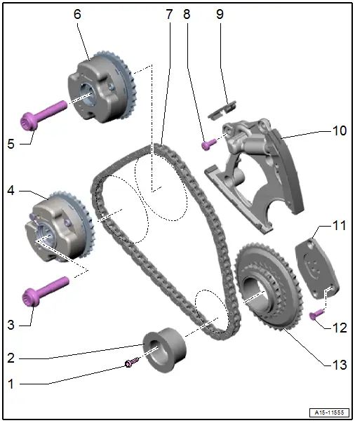
1 - Bolts
- Tightening specification. Refer to -item 4-
2 - Mounting Pin
- For the left camshaft timing chain drive chain sprocket
3 - Bolt
- 80 Nm +90º
- Replace after removing
4 - Camshaft Adjuster
- For the exhaust camshaft
- Designation "EX"
- Removing and installing. Refer to → Chapter "Camshaft Timing Chain, Removing from Camshafts".
5 - Bolt
- 80 Nm +90º
- Replace after removing
6 - Camshaft Adjuster
- For the intake camshaft
- Designation "IN"
- Removing and installing. Refer to → Chapter "Camshaft Timing Chain, Removing from Camshafts".
7 - Left Camshaft Timing Chain
- Mark the running direction with paint for reinstallation
- Removing from the camshafts. Refer to → Chapter "Camshaft Timing Chain, Removing from Camshafts".
- Removing and installing. Refer to → Chapter "Camshaft Timing Chain, Removing and Installing".
8 - Bolt
- 9 Nm
9 - Gliding Piece
10 - Chain Tensioner
- For the left camshaft timing chain
- Removing and installing. Refer to → Chapter "Camshaft Timing Chain, Removing and Installing".
11 - Bearing Plate
- For the drive chain sprocket
12 - Bolt
- Tightening specification. Refer to -item 8-
13 - Drive Chain Sprocket
- For the left camshaft timing chain
Right Camshaft Timing Chain
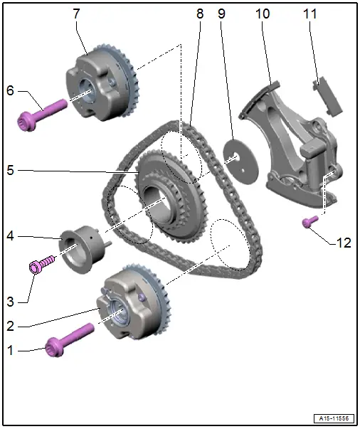
1 - Bolt
- 80 Nm +90º
- Replace after removing
2 - Camshaft Adjuster
- For the exhaust camshaft
- Designation "EX"
- Removing and installing. Refer to → Chapter "Camshaft Timing Chain, Removing from Camshafts".
3 - Bolt
- Tightening specification. Refer to -item 11-.
4 - Mounting Pin
- For the right camshaft timing chain drive chain sprocket
- Asymmetrical version
- Installation position. Refer to → Fig. "Mounting Pin for Right Camshaft Timing Chain Drive Chain Sprocket Installation Position".
5 - Drive Chain Sprocket
- For the right camshaft timing chain
- Installation position. Refer to → Fig. "Mounting Pin for Right Camshaft Timing Chain Drive Chain Sprocket Installation Position".
6 - Bolt
- 80 Nm +90º
- Replace after removing
7 - Camshaft Adjuster
- For the intake camshaft
- Designation "IN"
- Removing and installing. Refer to → Chapter "Camshaft Timing Chain, Removing from Camshafts".
8 - Right Camshaft Timing Chain
- Mark the running direction with paint for reinstallation
- Removing from the camshafts. Refer to → Chapter "Camshaft Timing Chain, Removing from Camshafts".
- Removing and installing. Refer to → Chapter "Camshaft Timing Chain, Removing and Installing".
9 - Thrust Washer
- For the right camshaft timing chain drive chain sprocket
- Asymmetrical version
- Installation position. Refer to → Fig. "Mounting Pin for Right Camshaft Timing Chain Drive Chain Sprocket Installation Position".
10 - Chain Tensioner
- For the right camshaft timing chain
- Removing and installing. Refer to → Chapter "Camshaft Timing Chain, Removing and Installing".
11 - Gliding Piece
12 - Bolt
- 9 Nm
Overview - Timing Mechanism Drive Chain
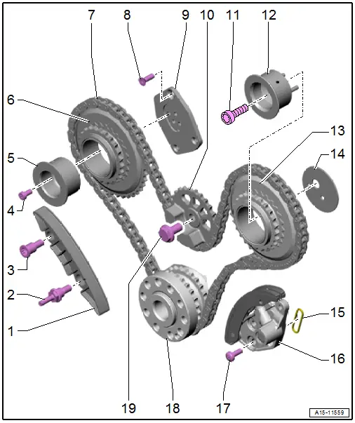
1 - Guide Rail
2 - Bolt
- 16 Nm
3 - Bolt
- 16 Nm
4 - Bolts
- 5 Nm +90º
- Replace after removing
5 - Mounting Pin
- For the left camshaft timing chain drive chain sprocket
6 - Drive Chain Sprocket
- For the left camshaft timing chain
7 - Drive Chain
- For timing mechanism
- Mark the running direction with paint for reinstallation
- Removing and installing. Refer to → Chapter "Timing Mechanism Drive Chain, Removing and Installing".
8 - Bolt
- 8 Nm +45º
- Replace after removing
9 - Bearing Plate
- For the left camshaft timing chain drive chain sprocket
10 - Balance Shaft Chain Sprocket
- With transmission side balance weight
11 - Bolt
- 30 Nm +90º
12 - Mounting Pin
- For the right camshaft timing chain drive chain sprocket
- Asymmetrical version
- Installation position. Refer to → Fig. "Mounting Pin for Right Camshaft Timing Chain Drive Chain Sprocket Installation Position".
13 - Drive Chain Sprocket
- For the right camshaft timing chain
- Installation position. Refer to → Fig. "Mounting Pin for Right Camshaft Timing Chain Drive Chain Sprocket Installation Position".
14 - Thrust Washer
- For the right camshaft timing chain drive chain sprocket
- Asymmetrical version
- Installation position. Refer to → Fig. "Mounting Pin for Right Camshaft Timing Chain Drive Chain Sprocket Installation Position".
15 - Seal
- Replace after removing
16 - Chain Tensioner
- Removing and installing. Refer to → Chapter "Timing Mechanism Drive Chain, Removing and Installing".
17 - Bolt
- 9 Nm
18 - Crankshaft
19 - Bolt
- Tightening specification. Refer to -item 2-.
Mounting Pin for Right Camshaft Timing Chain Drive Chain Sprocket Installation Position
- The alignment pins in the right camshaft timing chain drive chain sprocket mounting pin -3- must engage in the holes in the thrust washer -1- and in the cylinder block.
2 - Drive Chain Sprocket for Right Camshaft Timing Chain
4 - Bolt
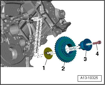
Overview - Oil Pump Drive Chain
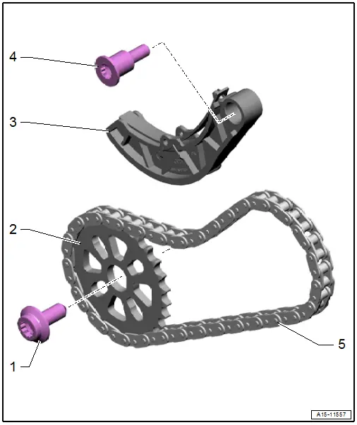
1 - Bolt
- 30 Nm +90º
- Replace after removing
2 - Drive Chain Sprocket
- For the oil pump
- Installed position: the side with the lettering faces the transmission
- Installation only possible in one position.
3 - Chain Tensioner
- With glide rail
4 - Bolt
- 20 Nm
5 - Drive Chain
- For the oil pump
- Mark the running direction with paint for reinstallation
- Removing and installing. Refer to → Chapter "Oil Pump Drive Chain, Removing and Installing".

