Audi Q7: Component Location Overview - Antenna Systems
Component Location Overview - Antenna Systems, Europe and Rest of World
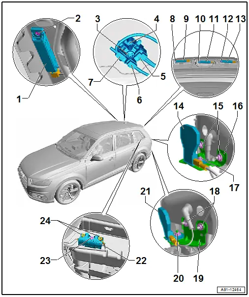
1 - Antenna Amplifier 3 -R112-
- Removing and Installing. Refer to → Chapter "Antenna Amplifier 3 -R112-, Removing and Installing".
2 - Bolt
- 2 Nm
3 - Nut
- 5 Nm
4 - Roof Antenna -R216-
- Removing and Installing. Refer to → Chapter "Roof Antenna, Removing and Installing".
5 - GPS Connection from GPS Antenna -R50-
6 - GSM Connection from Telephone Antenna -R65-
- LTE connection from LTE Antenna 2 -R306-
7 - RC Connection from Auxiliary Heater Antenna -R182-/Parking Heater Antenna Amplifier -R305-
8 - Bolt
- 2 Nm
9 - Antenna Amplifier 2 -R111-
- Removing and Installing. Refer to → Chapter "Top Antenna Amplifiers -R24-/-R111-/- R82-, Removing and Installing".
10 - Bolt
- 2 Nm
11 - TV Antenna Amplifier 1 -R82-
- Removing and Installing. Refer to → Chapter "Top Antenna Amplifiers -R24-/-R111-/- R82-, Removing and Installing".
12 - Bolt
- 2 Nm
13 - Antenna Amplifier -R24-
- Removing and Installing. Refer to → Chapter "Top Antenna Amplifiers -R24-/-R111-/- R82-, Removing and Installing".
14 - Telephone Antenna -R65-
- Removing and Installing. Refer to → Chapter "Bumper Antennas, Removing and Installing".
15 - Nut
- 4 Nm
- Quantity: 2
16 - Bracket
17 - Nut
- 4 Nm
18 - Nut
- 4 Nm
- Quantity: 2
19 - Bracket
20 - Nut
- 4 Nm
21 - LTE Antenna 1 -R297-
- Removing and Installing. Refer to → Chapter "Bumper Antennas, Removing and Installing".
22 - Windshield Antenna Suppression Filter -C18-
- Removing and Installing. Refer to → Chapter "Windshield Antenna Suppression Filter, Removing and Installing".
23 - Bolt
- 6 Nm
24 - Nut
- 9 Nm
- Quantity: 2
Component Location Overview - Antenna Systems, USA

1 - Not Installed
2 - Not Installed
3 - Nut
- 5 Nm
4 - Roof Antenna -R216-
- Removing and Installing. Refer to → Chapter "Roof Antenna, Removing and Installing".
5 - GPS Connection from GPS Antenna -R50-
6 - GSM Connection from Telephone Antenna -R65-
- LTE connection from LTE Antenna 2 -R306-
7 - SAT Connection for the Satellite Antenna -R170-
8 - Bolt
- 2 Nm
9 - Antenna Amplifier 2 -R111-
- Removing and Installing. Refer to → Chapter "Top Antenna Amplifiers -R24-/-R111-/- R82-, Removing and Installing".
10 - Bolt
- 2 Nm
11 - TV Antenna Amplifier 1 -R82-
- Removing and Installing. Refer to → Chapter "Top Antenna Amplifiers -R24-/-R111-/- R82-, Removing and Installing".
12 - Bolt
- 2 Nm
13 - Antenna Amplifier -R24-
- Removing and Installing. Refer to → Chapter "Top Antenna Amplifiers -R24-/-R111-/- R82-, Removing and Installing".
14 - LTE Antenna 2 -R306-
- Removing and Installing. Refer to → Chapter "Bumper Antennas, Removing and Installing".
15 - Nut
- 4 Nm
- Quantity: 2
16 - Bracket
17 - Nut
- 4 Nm
18 - Nut
- 4 Nm
- Quantity: 2
19 - Bracket
20 - Nut
- 4 Nm
21 - LTE Antenna 1 -R297-
- Removing and Installing. Refer to → Chapter "Bumper Antennas, Removing and Installing".
22 - Windshield Antenna Suppression Filter -C18-
- Removing and Installing. Refer to → Chapter "Windshield Antenna Suppression Filter, Removing and Installing".
23 - Bolt
- 6 Nm
24 - Nut
- 9 Nm
- Quantity: 2

