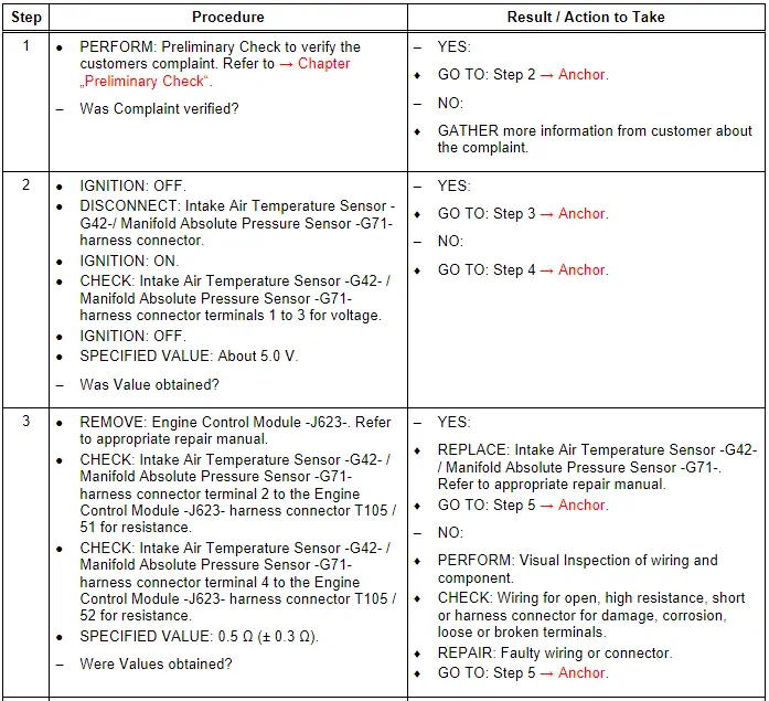
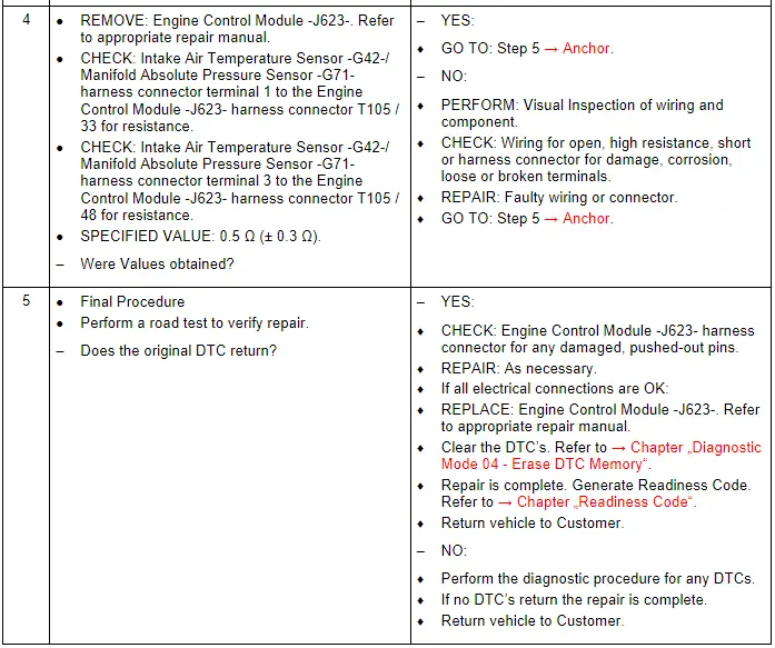
Audi Q7: Intake Air Temperature Sensor - G42- / Manifold Absolute Pressure Sensor - G71-, Checking
General Description
Air mass and charge pressure are two factors used for engine load management. For this purpose, there are several sensors with absolutely identical functions. They measure the intake air temperature and the intake manifold pressure. The Intake Air Temperature Sensor -G42- / Manifold Absolute Pressure Sensor -G71- is located upstream of the Throttle Valve Control Module -J338-. They measure the pressure and temperature of the air in each individual cylinder bank. The values measured here correspond to the actual air mass in the cylinder bank(s).
Special tools and workshop equipment required
- Multimeter.
- Wiring Diagram.
- Scan Tool.
Test requirements
- Fuses OK.
- Battery voltage OK.
- Switch OFF all electrical and electronic accessories.
- Vehicles with automatic transmission, ensure the selector lever position is in "P".
- Vehicles with manual transmission, ensure the shifter lever position is in "N" with the parking brake applied.
- Coolant temperature: ≥ 80º C.
- Observe all safety precautions: → Chapter "Safety Precautions".
- View clean working conditions: → Chapter "Clean Working Conditions".
- For Hybrid vehicles, refer to: → Chapter "High Voltage System General Warnings".
Test Procedure
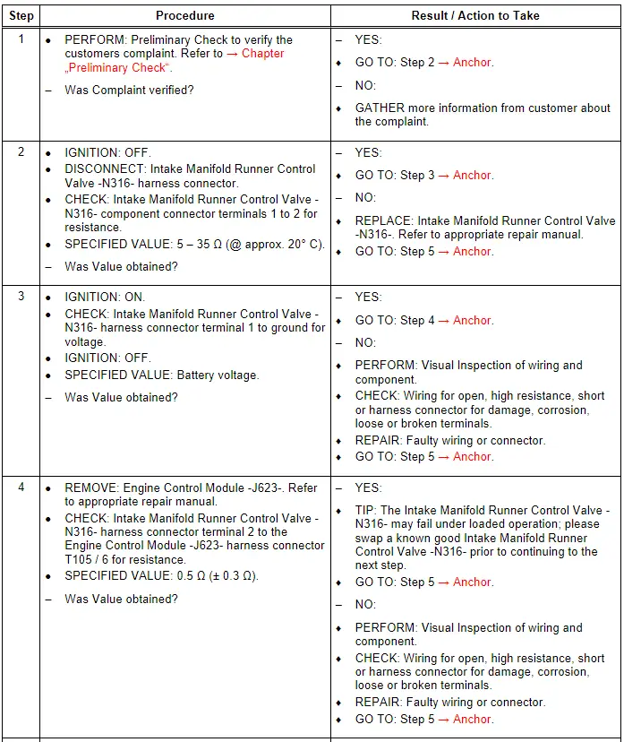
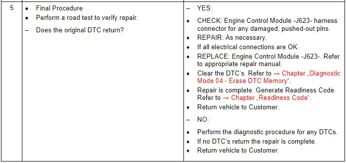
Intake Manifold Runner Control Valve - N316-, Checking
General Description
The intake manifold runner valve(s) are mounted on a common shaft and actuated by a vacuum cell. The partial vacuum required for actuation is supplied by the Intake Manifold Runner Control Valve -N316-. The Engine Control Module -J623- activates the Intake Manifold Runner Control Valve -N316- on the basis of a characteristic map.
Special tools and workshop equipment required
- Multimeter.
- Wiring Diagram.
- Scan Tool.
Test requirements
- Fuses OK.
- Battery voltage OK.
- Switch OFF all electrical and electronic accessories.
- Vehicles with automatic transmission, ensure the selector lever position is in "P".
- Vehicles with manual transmission, ensure the shifter lever position is in "N" with the parking brake applied.
- Coolant temperature: ≥ 80º C.
- Observe all safety precautions: → Chapter "Safety Precautions".
- View clean working conditions: → Chapter "Clean Working Conditions".
- For Hybrid vehicles, refer to: → Chapter "High Voltage System General Warnings".
Test Procedure
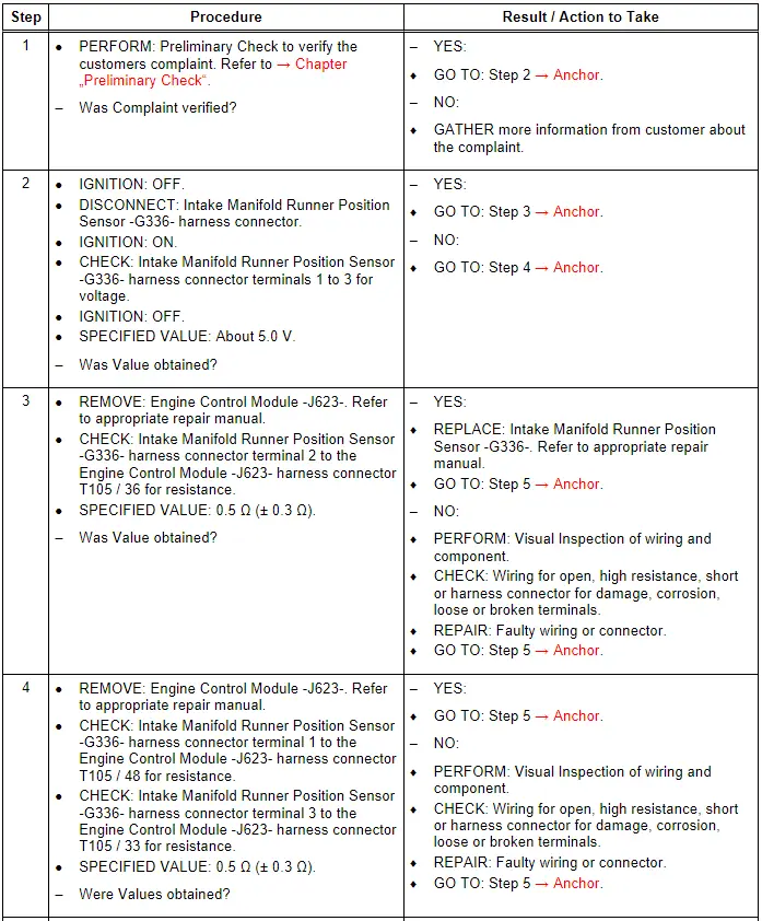
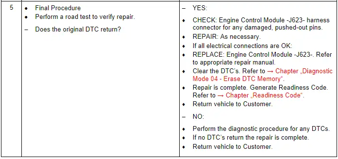
Intake Manifold Runner Position Sensor - G336-, Checking
General Description
The Intake Manifold Runner Position Sensor -G336- monitors the position of the intake manifold runner flaps. These flaps can be adjusted open or closed to provide longer or shorter intake runners depending on ambient conditions to increase engine efficiency.
Special tools and workshop equipment required
- Multimeter.
- Wiring Diagram.
- Scan Tool.
Test requirements
- Fuses OK.
- Battery voltage OK.
- Switch OFF all electrical and electronic accessories.
- Vehicles with automatic transmission, ensure the selector lever position is in "P".
- Vehicles with manual transmission, ensure the shifter lever position is in "N" with the parking brake applied.
- Coolant temperature: ≥ 80º C.
- Observe all safety precautions: → Chapter "Safety Precautions".
- View clean working conditions: → Chapter "Clean Working Conditions".
- For Hybrid vehicles, refer to: → Chapter "High Voltage System General Warnings".
Test Procedure
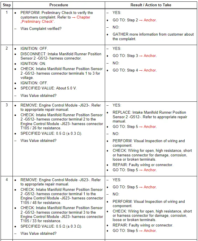
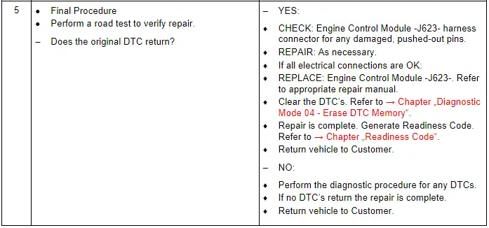
Intake Manifold Runner Position Sensor 2 - G512-, Checking
General Description
The Engine Control Module -J623- uses the Intake Manifold Runner Position Sensor 2 -G512- signal to calculate a correction value for the charge air pressure. Evaluation of the signal gives consideration to the influence of temperature on the density of the charge air.
Special tools and workshop equipment required
- Multimeter.
- Wiring Diagram.
- Scan Tool.
Test requirements
- Fuses OK.
- Battery voltage OK.
- Switch OFF all electrical and electronic accessories.
- Vehicles with automatic transmission, ensure the selector lever position is in "P".
- Vehicles with manual transmission, ensure the shifter lever position is in "N" with the parking brake applied.
- Coolant temperature: ≥ 80º C.
- Observe all safety precautions: → Chapter "Safety Precautions".
- View clean working conditions: → Chapter "Clean Working Conditions".
- For Hybrid vehicles, refer to: → Chapter "High Voltage System General Warnings".
Test Procedure