Audi Q7: Control Modules
Component Location Overview - Control Modules
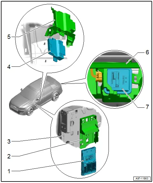
1 - Vehicle Electrical System Control Module -J519-
- Removing and installing. Refer to → Chapter "Vehicle Electrical System Control Module -J519-, Removing and Installing".
2 - Mount
- For Vehicle Electrical System Control Module -J519-
- Removing and installing. Refer to → Chapter "Vehicle Electrical System Control Module -J519- Mount, Removing and Installing".
3 - Left A-Pillar
4 - Data Bus On Board Diagnostic Interface -J533- - Low
- There are different versions. Refer to the Parts Catalog.
- Overview. Refer to → Chapter "Overview - Data Bus on Board Diagnostic Interface".
5 - Mount
- There are different versions. Refer to the Parts Catalog.
- For Data Bus on Board Diagnostic Interface -J533-
6 - Mount
- for the rear bumper cover
7 - Garage Door Opener Control Module -J530-
- Removing and installing. Refer to → Chapter "Garage Door Opener Control Module, Removing and Installing".
Overview - Data Bus on Board Diagnostic Interface
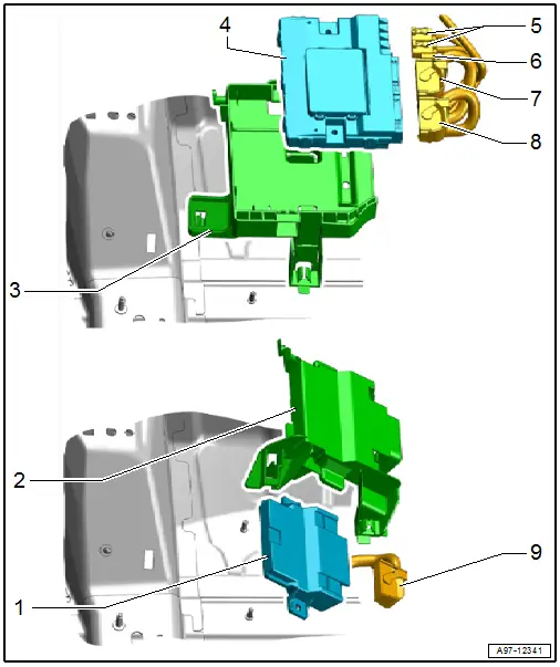
1 - Data Bus On Board Diagnostic Interface -J533- - Low
- Removing and installing. Refer to → Chapter "Data Bus On Board Diagnostic Interface -J533-, Removing and Installing, Low Version".
2 - Mount
- For Data Bus On Board Diagnostic Interface -J533- - Low
3 - Mount
- For Data Bus On Board Diagnostic Interface -J533- - High
4 - Data Bus On Board Diagnostic Interface -J533- - High
- Removing and installing. Refer to → Chapter "Data Bus On Board Diagnostic Interface -J533-, Removing and Installing, High Version".
5 - Fiber Optic Cable Connector
- Quantity: 2
- Seal with Fiber-Optic Repair Set - Connector Protective Caps -VAS6223/9-
6 - Antenna Wire Connector
7 - Connector
- For Data Bus On Board Diagnostic Interface -J533- - High
8 - Connector
- For Data Bus On Board Diagnostic Interface -J533- - High
9 - Connector
- For Data Bus On Board Diagnostic Interface -J533- - Low
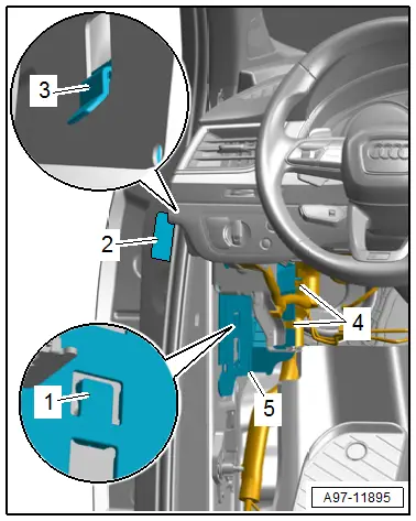
Vehicle Electrical System Control Module -J519-, Removing and Installing
Vehicle Electrical System Control Module -J519-, Removing and Installing
- If replacing the control module, select the "Replace control module" function for the corresponding control module on the Vehicle Diagnostic Tester.
Removing
- Remove the driver side instrument panel cover. Refer to → Body Interior; Rep. Gr.68; Storage Compartments and Covers; Driver Side Instrument Panel Cover, Removing and Installing.
- Remove the A-pillar lower trim panel. Refer to → Body Interior; Rep. Gr.70; Vehicle Interior Trim Panels; A-Pillar Trim Panel, Removing and Installing.
- Release the retainer -1-.
- Pull the vehicle electrical system control module -2- slightly downward.
- Disconnect the connectors -3, 4 and 5-.
- Remove the vehicle electrical system control module downward from the mount -6-.
Installing
Install in reverse order of removal.
Vehicle Electrical System Control Module -J519- Mount, Removing and Installing
Removing
- Remove the vehicle electrical system control module. Refer to → Chapter "Vehicle Electrical System Control Module -J519-, Removing and Installing".
- Free up the wiring harness -4-.
- Pry up the cover -2-.
- Release the catch -1- and push the mount -5- upward until the guides -3- are disengaged.
- Remove the mount downward.
Installing
Install in reverse order of removal.
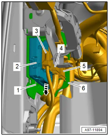
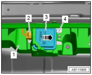
Garage Door Opener Control Module, Removing and Installing
Removing
- Remove the rear bumper cover. Refer to → Body Exterior; Rep. Gr.63; Rear Bumper; Bumper Cover, Removing and Installing.
- Disconnect the connector -2-.
- Release the retainer -4-.
- Remove the control module -3- from the mount -1- in direction of -arrow-.
Installing
Install in reverse order of removal.
Data Bus on Board Diagnostic Interface -J533-, Removing and Installing
Data Bus On Board Diagnostic Interface -J533-, Removing and Installing, Low Version
- If replacing the control module, select the "Replace control module" function for the corresponding control module on the Vehicle Diagnostic Tester.
Removing
- Remove the carpet on the driver side. Refer to → Body Interior; Rep. Gr.70; Vehicle Interior Trim Panels; Carpet, Removing and Installing.
- Release the catch -2- and remove the mount -3- from the threaded pin -1-.
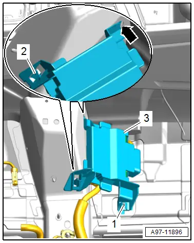
- Guide out the mount from the body -arrow-.
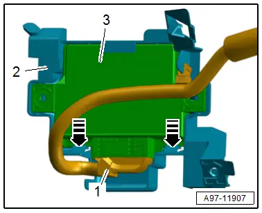
- Release the retainers in direction of -arrows-.
- Remove the data bus on board diagnostic interface -3- from the mount -2-.
- Disconnect the connector -1-.
Installing
Install in reverse order of removal.
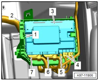
Data Bus On Board Diagnostic Interface -J533-, Removing and Installing, High Version
- If replacing the control module, select the "Replace control module" function for the corresponding control module on the Vehicle Diagnostic Tester.
Removing
- Remove the carpet on the driver side. Refer to → Body Interior; Rep. Gr.70; Vehicle Interior Trim Panels; Carpet, Removing and Installing.
- Release the retainers -1-.
- Remove the data bus on board diagnostic interface -3- from the mount -2-.
- Disconnect the connectors -6 and 7- and antenna wires -4 and 5-.
Installing
Install in reverse order of removal.

