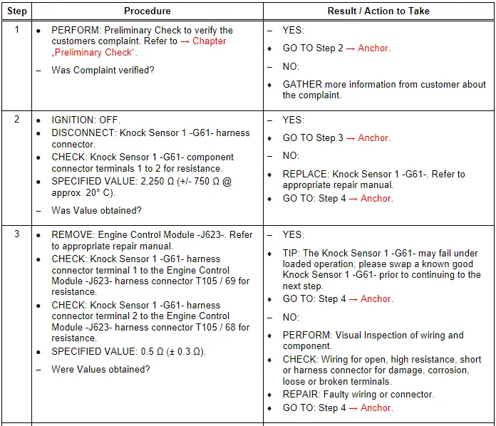
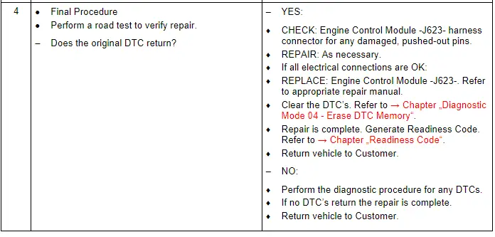
Audi Q7: Knock Sensor 1 - G61-, Checking
General Description
The Knock Sensor 1 -G61- is a tuned accelerometer on the engine which converts engine vibration to an electrical signal. The Engine Control Module -J623- uses this signal to determine the presence of engine knock and to retard spark timing, if necessary.
Special tools and workshop equipment required
- Multimeter.
- Wiring Diagram.
- Scan Tool.
Test requirements
- Fuses OK.
- Battery voltage OK.
- Switch OFF all electrical and electronic accessories.
- Vehicles with automatic transmission, ensure the selector lever position is in "P".
- Vehicles with manual transmission, ensure the shifter lever position is in "N" with the parking brake applied.
- Coolant temperature: ≥ 80º C.
- Observe all safety precautions: → Chapter "Safety Precautions".
- View clean working conditions: → Chapter "Clean Working Conditions".
- For Hybrid vehicles, refer to: → Chapter "High Voltage System General Warnings".
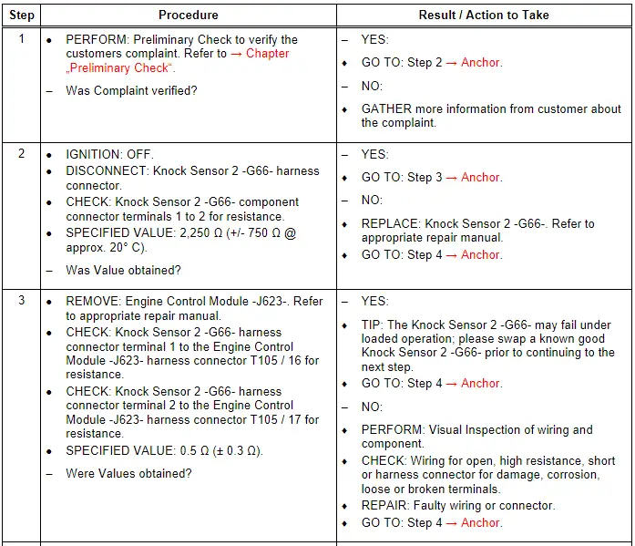
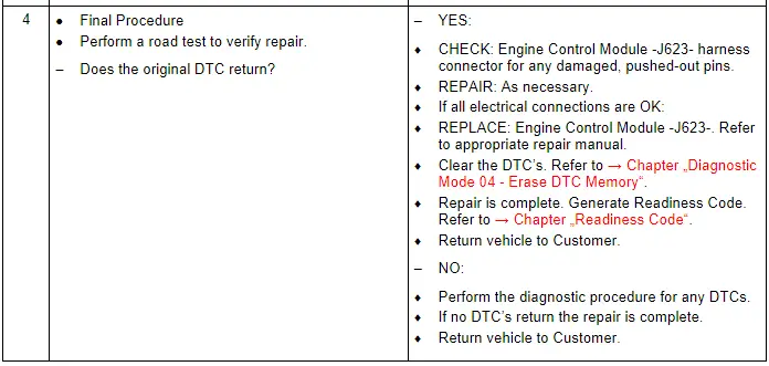
Knock Sensor 2 - G66-, Checking
General Description
The Knock Sensor 2 -G66- is a tuned accelerometer on the engine which converts engine vibration to an electrical signal. The Engine Control Module -J623- uses this signal to determine the presence of engine knock and to retard spark timing, if necessary.
Special tools and workshop equipment required
- Multimeter.
- Wiring Diagram.
- Scan Tool.
Test requirements
- Fuses OK.
- Battery voltage OK.
- Switch OFF all electrical and electronic accessories.
- Vehicles with automatic transmission, ensure the selector lever position is in "P".
- Vehicles with manual transmission, ensure the shifter lever position is in "N" with the parking brake applied.
- Coolant temperature: ≥ 80º C.
- Observe all safety precautions: → Chapter "Safety Precautions".
- View clean working conditions: → Chapter "Clean Working Conditions".
- For Hybrid vehicles, refer to: → Chapter "High Voltage System General Warnings".
Test Procedure
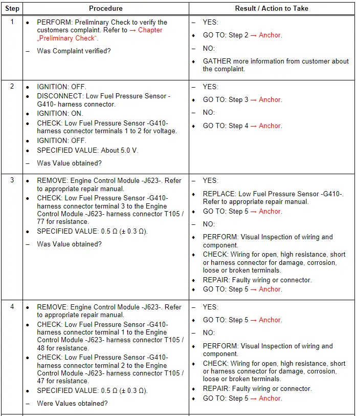
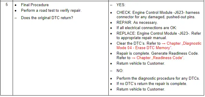
Low Fuel Pressure Sensor - G410-, Checking
General Description
The low-side fuel pressure is constantly monitored by the Low Fuel Pressure Sensor -G410- and sent to the Engine Control Module -J623-. If this pressure deviates from the desired pressure, the Engine Control Module -J623- sends a signal to the Fuel Pump Control Module -J538-. The Fuel Pump Control Module -J538- then sends a PWM signal to the Transfer Fuel Pump -G6- until the desired fuel pressure is achieved.
Special tools and workshop equipment required
- Multimeter.
- Wiring Diagram.
- Scan Tool.
Test requirements
- Fuses OK.
- Battery voltage OK.
- Switch OFF all electrical and electronic accessories.
- Vehicles with automatic transmission, ensure the selector lever position is in "P".
- Vehicles with manual transmission, ensure the shifter lever position is in "N" with the parking brake applied.
- Coolant temperature: ≥ 80º C.
- Observe all safety precautions: → Chapter "Safety Precautions".
- View clean working conditions: → Chapter "Clean Working Conditions".
- For Hybrid vehicles, refer to: → Chapter "High Voltage System General Warnings".
Test Procedure
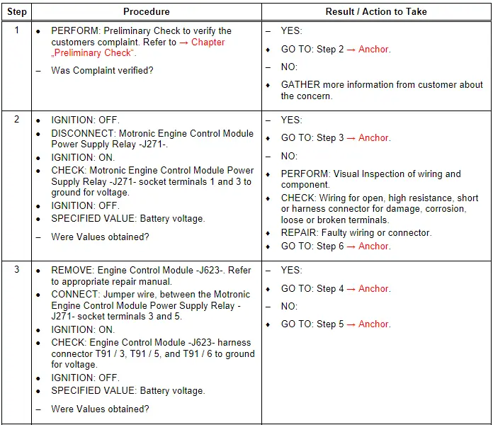
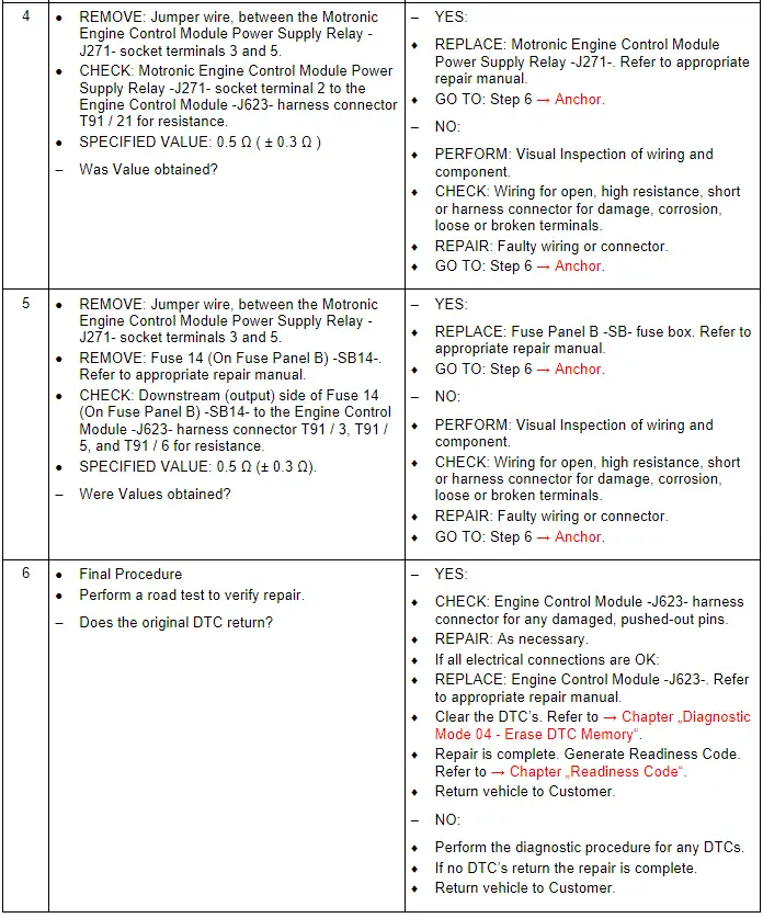
Motronic Engine Control Module Power Supply Relay - J271 -, Checking
General Description
The following procedure is used to diagnose the Motronic Engine Control Module Power Supply Relay -J271- and the Engine Control Module -J623- power supply voltage that is provided by the Motronic Engine Control Module Power Supply Relay -J271-.
Special tools and workshop equipment required
- Multimeter.
- Wiring Diagram.
- Scan Tool.
Test requirements
- Fuses OK.
- Battery voltage OK.
- Switch OFF all electrical and electronic accessories.
- Vehicles with automatic transmission, ensure the selector lever position is in "P".
- Vehicles with manual transmission, ensure the shifter lever position is in "N" with the parking brake applied.
- Coolant temperature: ≥ 80º C.
- Observe all safety precautions: → Chapter "Safety Precautions".
- View clean working conditions: → Chapter "Clean Working Conditions".
- For Hybrid vehicles, refer to: → Chapter "High Voltage System General Warnings".
Test Procedure