Audi Q7: Pedestrian Protection Crash Sensor, Removing and Installing
Removing
 WARNING
Follow all safety precautions when working on pyrotechnic components. Refer to → Chapter "Safety Precautions for Pyrotechnic Components".
- Disconnect the battery ground cable with the ignition turned on. Refer to → Electrical Equipment; Rep. Gr.27; Battery; Battery, Disconnecting and Connecting.
- Remove the front bumper cover. Refer to → Body Exterior; Rep. Gr.63; Front Bumper; Bumper Cover, Removing and Installing.
 WARNING
Before handling pyrotechnic components (for example, disconnecting the connector), the person handling it must "discharge static electricity". This can be done by briefly touching the door striker pin, for example.
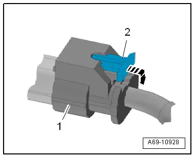
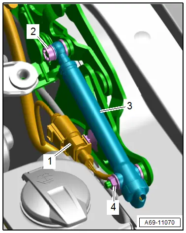
- To do this pull out the connector lock -2-, push down in direction of -arrow-, and disconnect the connector -1- on the crash sensor.
- Repeat the process on the opposite side.
- Remove the molded foam piece. Refer to → Body Exterior; Rep. Gr.63; Front Bumper; Attachments, Removing and Installing.
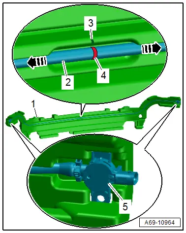
- Disengage the pedestrian protection crash sensor -5- from the molded foam part -1-.
Installing
 WARNING
- Follow all safety precautions when working on pyrotechnic components. Refer to → Chapter "Safety Precautions for Pyrotechnic Components".
- Before handling pyrotechnic components (for example, connecting the connector), the person handling it must "discharge static electricity". This can be done by briefly touching the door striker pin, for example.
- Position the pressure hose -2- at the center of the color mark -4- in the recess at the specified marking -3- in the molded foam part -1-.
 Note
Note- There are pressure hoses -2- without and with the color mark -4-.
- For a pressure hose -2- without a color mark -4-, measure the center and mark it.
- Position the pressure hose equally in both directions -arrows- in the recess in the molded foam part.
 WARNING
Do not kink or stretch the pressure hose.
- Engage the pedestrian protection crash sensor into the molded foam part.
- Install the molded foam piece with the pedestrian protection crash sensor. Refer to → Body Exterior; Rep. Gr.63; Front Bumper; Attachments, Removing and Installing.
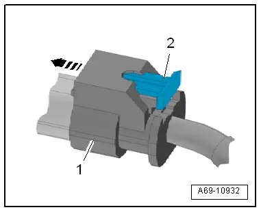
- Connect the connector -1- to the crash sensor until it clicks into place in direction of -arrow-.
- Push in the connector lock -2- to secure the connector.
Installation is performed in reverse order of removal, while noting the following:
 Note
Note- Make sure the connectors are pushed in all the way and that they engage audibly.
- Make sure the wires are not pinched.
 WARNING
Repairing pyrotechnic components (for example the airbag and seat belt tensioner) incorrectly increases the risk of unintentional deployments when the battery is connected.
- The ignition must be on when connecting the battery.
- For personal safety when connecting the battery, stay out of the deployment area of the airbag and maintain a distance from the seat belt tensioners/seat belts.
- Make sure that there are no other people inside the vehicle at the time when the battery is connected.
- Connect the battery ground cable with the ignition turned on. Refer to → Electrical Equipment; Rep. Gr.27; Battery; Battery, Disconnecting and Connecting.
 Note
Note
If the Airbag Indicator Lamp -K75- indicates a fault, check the Diagnostic Trouble Code (DTC) memory, erase it and check it again using the Vehicle Diagnostic Tester.
Installation notes, for example tightening specifications, replacing components. Refer to → Chapter "Overview - Pedestrian Protection".
Pedestrian Protection Trigger 1 -G598-/ Pedestrian Protection Trigger 2 -G599-, Removing and Installing
Removing
 WARNING
Follow all safety precautions when working on pyrotechnic components. Refer to → Chapter "Safety Precautions for Pyrotechnic Components".
- Disconnect the battery ground cable with the ignition turned on. Refer to → Electrical Equipment; Rep. Gr.27; Battery; Battery, Disconnecting and Connecting.
- Remove the plenum chamber cover. Refer to → Body Exterior; Rep. Gr.50; Bulkhead; Plenum Chamber Cover, Removing and Installing.
 WARNING
Before handling pyrotechnic components (for example, disconnecting the connector), the person handling it must "discharge static electricity". This can be done by briefly touching the door striker pin, for example.
- Press the release to free up and disconnect the pedestrian protection trigger connector -1-.
- Remove the clip -2- with a screwdriver.
- Remove the nut -4-.
- Remove the pedestrian protection trigger -3- from the pin.
Installing
 WARNING
- Follow all safety precautions when working on pyrotechnic components. Refer to → Chapter "Safety Precautions for Pyrotechnic Components".
- Before handling pyrotechnic components (for example, connecting the connector), the person handling it must "discharge static electricity". This can be done by briefly touching the door striker pin, for example.
Further installation is the reverse order of removal.
 Note
Note- Make sure the connectors are pushed in all the way and that they engage audibly.
- Make sure the wires are not pinched.
 WARNING
Repairing pyrotechnic components (for example the airbag and seat belt tensioner) incorrectly increases the risk of unintentional deployments when the battery is connected.
- The ignition must be on when connecting the battery.
- For personal safety when connecting the battery, stay out of the deployment area of the airbag and maintain a distance from the seat belt tensioners/seat belts.
- Make sure that there are no other people inside the vehicle at the time when the battery is connected.
- Connect the battery ground cable with the ignition turned on. Refer to → Electrical Equipment; Rep. Gr.27; Battery; Battery, Disconnecting and Connecting.
 Note
Note
If the Airbag Indicator Lamp -K75- indicates a fault, check the Diagnostic Trouble Code (DTC) memory, erase it and check it again using the Vehicle Diagnostic Tester.
Installation notes, for example tightening specifications, replacing components. Refer to → Chapter "Overview - Pedestrian Protection".
Special Tools
Special tools and workshop equipment required
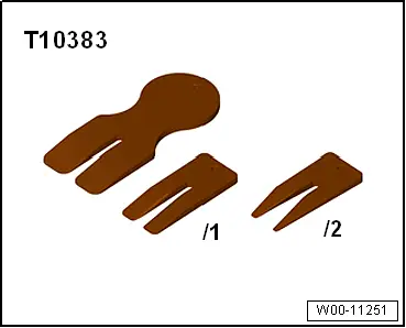
- Wedge Set -T10383-
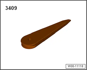
- Trim Removal Wedge -3409-
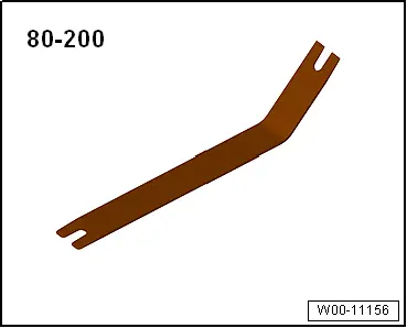
- Pry Lever -80-200-
- Not illustrated:
- Engine/Transmission Holder - Seat Repair Fixture -VAS6136-