Audi Q7: Overview - Front Door Trim Panel
Audi Q7 (4M) 2016-2026 Workshop Manual / Body / Body Interior / Interior Trim / Overview - Front Door Trim Panel
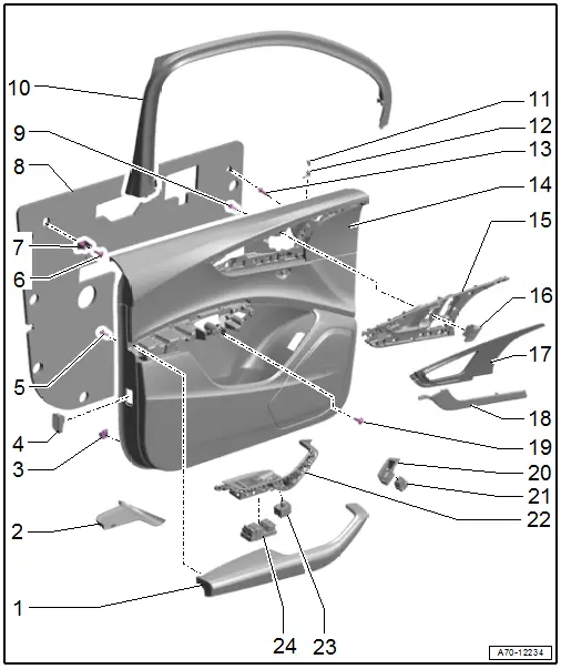
1 - Pull Handle with Armrest
- Removing and installing. Refer to → Chapter "Front Pull Handle, Removing and Installing".
2 - Liner Mat
- Insert in the door pocket.
3 - Clip
- For door trim panel
- Quantity: 9
- Insert in the trim panel
4 - Rear Reflector
- Driver side equipment level: Driver Door Warning Lamp -W30-
- Front passenger side equipment level: Front Passenger Door Warning Lamp -W36-
- Component location overview. Refer to → Electrical Equipment; Rep. Gr.96; Lamps; Overview - Component Location Front Door Lamps.
5 - Bolt
- 1.5 Nm
- For the armrest
- Quantity: 14
6 - Bolt
- 4.5 Nm
7 - Clip
- For door trim panel
8 - Insulation
9 - Bolt
- 1.5 Nm
- For the interior door mechanism
- Quantity: 13
10 - Window Frame Trim Panel
- Removing and installing. Refer to → Chapter "Window Frame Trim, Removing and Installing".
11 - Sleeve
- For Central Locking -SAFE- Indicator Lamp -K133-
- Driver door only
- When replacing the door trim panel, a hole for the sleeve must be made in the new panel using the old panel as a sample
12 - Central Locking -Safe- Indicator Lamp -K133-
13 - Door Trim Panel Stopper
- 5 Nm
14 - Door Trim Panel
- Removing and installing. Refer to → Chapter "Front Door Trim Panel, Removing and Installing".
- When replacing the door trim panel, a hole for the sleeve -11- must be made in the new panel using the old panel as a sample.
15 - Interior Door Mechanism
- Removing and installing. Refer to → Chapter "Interior Door Mechanism, Removing and Installing".
16 - Driver Interior Locking Button -E308-
- Front passenger side: Front Passenger Interior Locking Button -E309-
- Component location overview. Refer to → Electrical Equipment; Rep. Gr.96; Controls; Component Location Overview - Controls in Front Doors.
17 - Interior Door Mechanism Decorative Trim
- Removing and installing. Refer to → Chapter "Trim Molding, Removing and Installing".
18 - Decorative Trim
- Removing and installing. Refer to → Chapter "Trim Molding, Removing and Installing".
19 - Bolt
- 4.5 Nm
- For door trim panel
- Quantity: 3
20 - Switch Trim
- Removing and installing. Refer to → Electrical Equipment; Rep. Gr.96; Controls; Component Location Overview - Controls in Front Doors.
21 - Rear Lid Remote Release Button -E233-
- Removing and installing. Refer to → Electrical Equipment; Rep. Gr.96; Controls; Component Location Overview - Controls in Front Doors.
22 - Switch Mount
- Removing and installing. Refer to → Chapter "Front Pull Handle, Removing and Installing".
23 - Mirror Adjusting Switch -E43-
- With Mirror Selector Switch -E48-
- Component location overview. Refer to → Electrical Equipment; Rep. Gr.96; Controls; Component Location Overview - Controls in Front Doors.
24 - Power Window Control Head in Driver Door -E512-
- Passenger side: Front Passenger Power Window Button -E716-
- Component location overview. Refer to → Electrical Equipment; Rep. Gr.96; Controls; Component Location Overview - Controls in Front Doors.

