Audi Q7: Component Location Overview - Telephone System
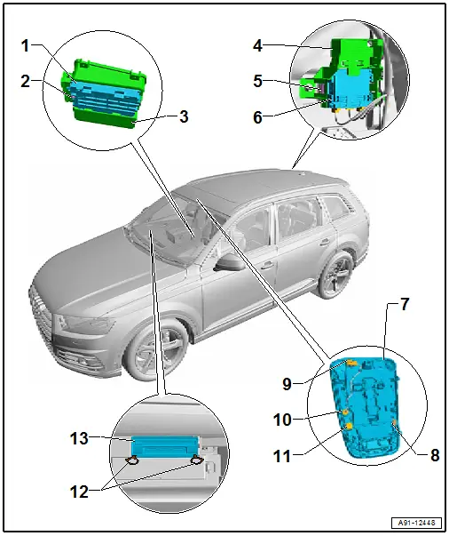
1 - Telephone Baseplate -R126-
- Removing and Installing. Refer to → Chapter "Telephone Baseplate -R126-, Removing and Installing".
- Wireless Charger
- Removing and Installing. Refer to → Chapter "Telephone Baseplate - R126-, Removing and Installing, Wireless Charger".
2 - Bolt
- 1 Nm
3 - Center Console Storage Compartment
- Removing and installing. Refer to → Body Interior; Rep. Gr.68; Center Console; Front Center Console Storage Compartment, Removing and Installing.
4 - Bracket
5 - Retainer
6 - Cellular Telephone Amplifier -R86-
- Connector Assignment. Refer to → Wiring diagrams, Troubleshooting & Component locations.
- Removing and Installing. Refer to → Chapter "Cellular Telephone Amplifier -R86-, Removing and Installing".
7 - Front Interior Lamp -W1-
- Microphone Unit in Front Roof Module -R164-
- Overview. Refer to → Chapter "Overview - Microphone Unit".
8 - Right Front Microphone -R141-
- Removing and Installing. Refer to → Chapter "Microphone Unit in Front Roof Module -R164-, Removing and Installing".
9 - 4-Pin Connector -T4ed-
10 - Interior Microphone -R74-
- Removing and Installing. Refer to → Chapter "Microphone Unit in Front Roof Module -R164-, Removing and Installing".
11 - Left Front Microphone -R140-
- Removing and Installing. Refer to → Chapter "Microphone Unit in Front Roof Module -R164-, Removing and Installing".
12 - Radio Removal Tool -T10057-
13 - Information Electronics Control Module 1 -J794-
- Connector Assignment. Refer to → Wiring diagrams, Troubleshooting & Component locations.
- Removing and Installing. Refer to → Chapter "Information Electronics Control Module 1 -J794-, Removing and Installing".
Overview - Microphone Unit
One microphone (Interior Microphone -R74-) is connected directly to the Digital Soand System Control Module -J525-. The other microphones are connected to the Information Electronics Control Module 1 -J794-.
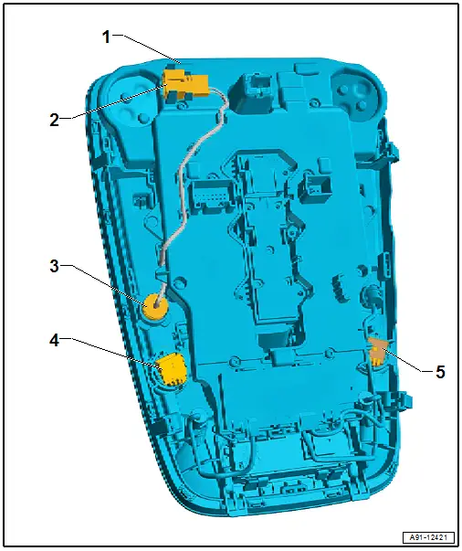
1 - Front Interior Lamp -W1-
- Removing and installing. Refer to → Electrical Equipment; Rep. Gr.96; Controls; Front Interior Lamp/Reading Lamp, Removing and Installing.
2 - 4-Pin Connector -T4ed-, black
3 - Interior Microphone -R74-
- Removing and Installing. Refer to → Chapter "Microphone Unit in Front Roof Module -R164-, Removing and Installing".
4 - Left Front Microphone -R140-
- 4-Pin Connector -T4fh-, red
- Removing and Installing. Refer to → Chapter "Microphone Unit in Front Roof Module -R164-, Removing and Installing".
5 - Right Front Microphone -R141-
- 4-Pin Connector -T4fl-, black
- Removing and Installing. Refer to → Chapter "Microphone Unit in Front Roof Module -R164-, Removing and Installing".
Microphone Unit in Front Roof Module -R164-, removing and installing. Refer to → Chapter "Microphone Unit in Front Roof Module -R164-, Removing and Installing".

