Audi Q7: Horn
Overview - Horn
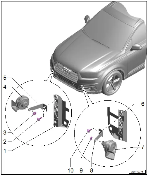
1 - Lock Carrier
2 - Bolt
- 8 Nm
3 - Nut
- 11 Nm
4 - High Tone Horn -H2-
- Removing and installing. Refer to → Chapter "High Tone Horn -H2-/Low Tone Horn -H7-, Removing and Installing".
5 - Bracket
- For the right horn
6 - Lock Carrier
7 - Low Tone Horn -H7-
- Removing and installing. Refer to → Chapter "High Tone Horn -H2-/Low Tone Horn -H7-, Removing and Installing".
8 - Bracket
- For the left horn
9 - Nut
- 11 Nm
10 - Bolt
- 8 Nm
High Tone Horn -H2-/Low Tone Horn -H7-, Removing and Installing
High Tone Horn -H2-/Low Tone Horn -H7-, Removing and Installing
Removing
- Remove the air intake grille. Refer to → Body Exterior; Rep. Gr.63; Front Bumper; Attachments, Removing and Installing.
- Remove the cap for the air intake grille. Refer to → Body Exterior; Rep. Gr.63; Front Bumper; Attachments, Removing and Installing.
- Vehicles with a sideways auxiliary radiator or charge air cooler: Push the air duct slightly to the side. If it is difficult to access remove the front bumper cover. Refer to → Body Exterior; Rep. Gr.63; Front Bumper; Bumper Cover Removing and Installing.
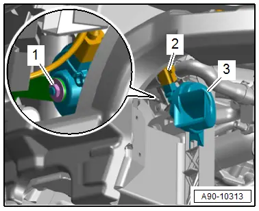
- Remove the nut -1-.
- Remove the horn -3- from the bracket.
- Disconnect the connector -2-.
Installing
Install in reverse order of removal.
Tightening Specifications
- Refer to → Chapter "Overview - Horn"
Horn Bracket, Removing and Installing
Removing
- Remove the air intake grille. Refer to → Body Exterior; Rep. Gr.63; Front Bumper; Attachments, Removing and Installing.
- Remove the cap for the air intake grille. Refer to → Body Exterior; Rep. Gr.63; Front Bumper; Attachments, Removing and Installing.
- Vehicles with a sideways auxiliary radiator or charge air cooler: Push the air duct slightly to the side. If it is difficult to access remove the front bumper cover. Refer to → Body Exterior; Rep. Gr.63; Front Bumper; Bumper Cover Removing and Installing.
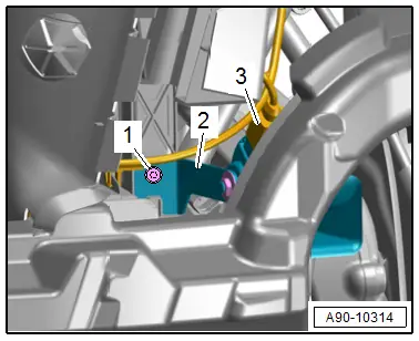
- Disconnect the connector -3-.
- Remove the bolt -1-.
- Remove the bracket -2- and the horn.
Installing
Install in reverse order of removal.
Tightening Specifications
- Refer to → Chapter "Overview - Horn"
Special Tools
Special tools and workshop equipment required
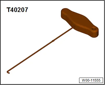
- Hook Tool -T40207- (High - Instrument Cluster Version)
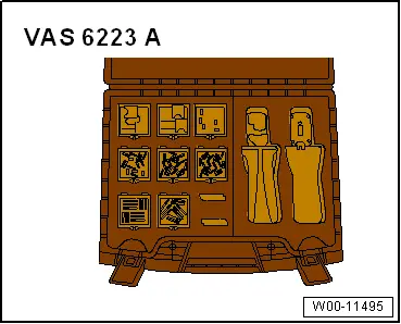
- Fiber-Optic Repair Set - Connector Protective Caps -VAS6223/9- from Fiber-Optic Repair Set -VAS6223B-
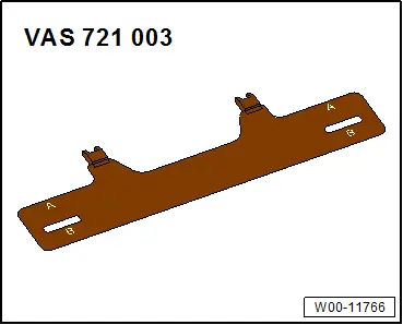
- Calibration Board for Head-Up Display VAS 721 003 -VAS721003-