Audi Q7 Owners & Service Manuals

Audi Q7: Overview - Bosch Generator from 2001

  Note

The generators were implemented as a running change.
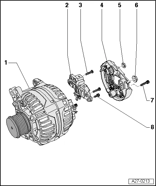
Overview - Bosch Generator from 2001

1 - Generator

2 - Voltage Regulator

  • Removing and installing. Refer to → Chapter "Voltage Regulator, Bosch Generator from 2001, Removing and Installing".
  • Carbon brushes, checking. Refer to → Chapter "Carbon Brushes, Checking, All Bosch Generators from 2001"

3 - Bolt

  • 2.5 Nm

4 - Cover

5 - Nut

  • 12 Nm

6 - Nut

  • 30 Nm

7 - Bolt

  • 3 Nm

8 - Bolt

  • 1.5 Nm

Voltage Regulator, Bosch Generator from 2001, Removing and Installing

Removing

- Remove the generator. Refer to → Electrical Equipment; Rep. Gr.27; Generator; Generator, Removing and Installing.

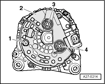
- Remove the bolt -1- and the nuts -3- and -4-.

- Remove the cover -2- on the rear side of the generator.

A27-0214

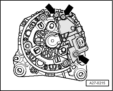
- Remove the bolts -arrows-.

- Remove voltage regulator.

A27-0215

Installing

- When installing the voltage regulator, make sure the carbon brushes rest correctly on the slip rings.

Install in reverse order of removal, observing the following:

- Install the generator. Refer to → Electrical Equipment; Rep. Gr.27; Generator; Generator, Removing and Installing.

  • Tightening specification. Refer to → Chapter "Overview - Bosch Generator from 2001".

    READ NEXT:

     Overview - Bosch Generator from 2007

      Note The new generators are installed as a running change. 1 - Nut 65 Nm 2 - Ribbed Belt Pulley 3 - Generator 4 - Voltage Regulator Removing and

     Overview - Generator, Valeo through MY 2000

    1 - Generator 2 - Voltage Regulator Removing: Remove the nuts -5- and the cover -4-. Remove the bolt -6- and the nuts -7- and remove the voltage regulator. Carbon brus

     Ribbed Belt Pulley without Freewheel, Removing and Installing

    Special tools and workshop equipment required Generator Belt Socket -3310- Inner hex socket 8 mm or TORX T50 Removing - Remove the generator if necessary. Refer to → Electrical Equip

    SEE MORE:

     Airbag Control Module

    Overview - Airbag Control Module 1 - Center Tunnel 2 - Nut 9 Nm Quantity: 4 The thread must be paint and contaminant free, nut and ground pins serve as ground connection for the control module. 3 - Airbag Control Module -J234- Removing and installing. Refer to

     Luggage compartment lid

    General information WARNING Applies to: vehicles with anti-theft alarm system: When the vehicle is locked from the outside, no one, especially children, should remain in the vehicle, because the windows can no longer open from the inside. Locked doors make it more difficult for emergency work

    © 2019-2025 Copyright www.a-q7.com