Audi Q7: Overview - Steering Gear
Audi Q7 (4M) 2016-2026 Workshop Manual / Chassis / Suspension, Wheels, Steering / Steering / Overview - Steering Gear
Overview - Steering Gear
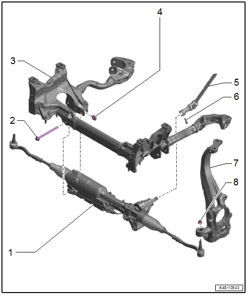
1 - Steering Gear with Tie Rods
- With integrated Power Steering Control Module -J500-
- The Power Steering Control Module -J500- cannot be replaced separately if faulty replace the steering gear.
- Removing and installing. Refer to → Chapter "Steering Gear, Removing and Installing".
- Servicing. Refer to → Chapter "Overview - Steering Gear, Tie Rods".
2 - Bolt
- 80 Nm +180º
- Replace after removing
3 - Subframe
4 - Nut
- Pushed into the subframe
- Replace after removing
5 - Steering Intermediate Shaft
- Removing and installing. Refer to → Chapter "Steering Intermediate Shaft, Removing and Installing".
6 - Bolt
- Tightening specification. Refer to -item 1-
7 - Wheel Bearing Housing
- Removing and installing. Refer to → Chapter "Wheel Bearing Housing, Removing and Installing".
8 - Nut
- 140 Nm
- Replace after removing
- After loosening remove the adhesive residue from the pin threads
Overview - Steering Gear, Tie Rods
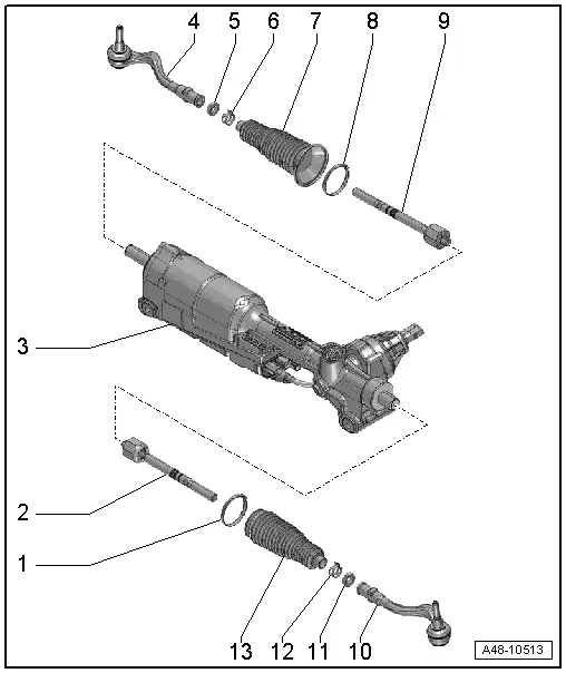
1 - Clamp
- Replace after removing
- Do not open the new clamp
- Tensioning.
2 - Tie Rod
- 100 Nm
- Grease the joint with Steering Gear Grease -G 052 168 A1-
- Removing and installing. Refer to → Chapter "Tie Rod, Removing and Installing".
3 - Steering Gear
- Grease the steering rack with Steering Gear Grease -G 052 168 A1-
- Removing and installing. Refer to → Chapter "Steering Gear, Removing and Installing".
4 - Tie Rod End
- Check dust cap for damage and correct seating.
- Check dimension. Refer to → Fig. "Tie Rod End Check Dimension"
- Removing and installing. Refer to → Chapter "Tie Rod End, Removing and Installing".
5 - Nut
- 80 Nm
- When loosening and tightening, counterhold at the tie rod end
6 - Spring Clamp
- Replace after removing
- Spring Clamp, Installing.
7 - Boot
- Check for damage
- Replace after removing
- Must not be twisted when toe is being adjusted
- Do not crumple the boot
- Make sure it is installed correctly. Refer to → Fig. "Tension the Inner Clamp Using the Clampling Pliers -VAG1682A-.".
- Replacing. Refer to → Chapter "Boot, Removing and Installing".
8 - Clamp
- Replace after removing
- Do not open the new clamp
- Tensioning. Refer to → Fig. "Tension the Inner Clamp Using the Clampling Pliers -VAG1682A-.".
9 - Tie Rod
- 100 Nm
- Grease the joint with Steering Gear Grease -G 052 168 A1-
- Removing and installing. Refer to → Chapter "Tie Rod, Removing and Installing".
10 - Tie Rod End
- Check dust cap for damage and correct seating.
- Check dimension. Refer to → Fig. "Tie Rod End Check Dimension"
- Removing and installing. Refer to → Chapter "Tie Rod End, Removing and Installing".
11 - Nut
- 80 Nm
- When loosening and tightening, counterhold at the tie rod end
12 - Spring Clamp
- Replace after removing
- Spring Clamp, Installing. Refer to → Fig. "Outer Boot Installation Position".
13 - Boot
- Check for damage
- Replace after removing
- Do not turn when toe is being adjusted
- Do not crumple the boot
- Do not bring into contact with hard or sharp objects.
- Installation position. Refer to → Fig. "Outer Boot Installation Position".
- Removing and installing. Refer to → Chapter "Boot, Removing and Installing".
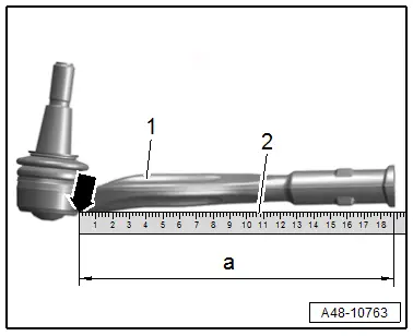
Tie Rod End Check Dimension
- Place a steel ruler -2- on the tie rod end and push it all the up to the edge -arrow- of the tie rod end -1-.
- Replace the complete steering gear with the tie rod and tie rod end if the check dimension -a- is less than 200 mm.
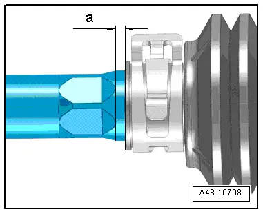
Outer Boot Installation Position
- Dimension -a- = 2 mm.
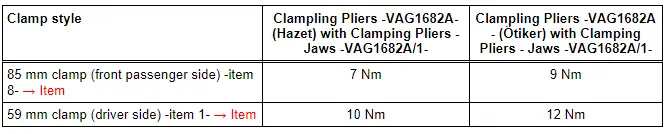
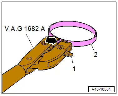
Tension the Inner Clamp Using the Clampling Pliers -VAG1682A-.
- Attach the Clampling Pliers -VAG1682A- as shown.
- The jaws on the pliers must be centered -arrow- on the clamp -2-.
 Note
Note
- The spindle threads must turn easily. If necessary, coat with MoS2 lubricating grease.
- If difficult to tighten, for example because of dirty threads, the proper clamping force of the clamping sleeve will not be reached even when tightened to the specification.
- Tension the clamp by turning the spindle -1- with the torque wrench, at the same time do not tilt the clamping pliers.
Tightening Specifications