Audi Q7: Sensors
Intake Air Temperature Sensor -G42-/Manifold Absolute Pressure Sensor -G71-, Removing and Installing
 Caution
This procedure contains mandatory replaceable parts. Refer to component overview prior to starting procedure.
Mandatory Replacement Parts
- O-ring - IAT/MAP sensor
Removing
- Remove the engine cover. Refer to → Chapter "Engine Cover, Removing and Installing".
- Disconnect the connectors -1 through 4-.
 Note
Note
Ignore -5-.
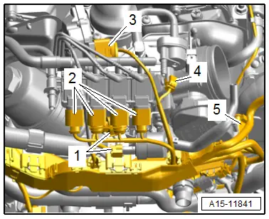
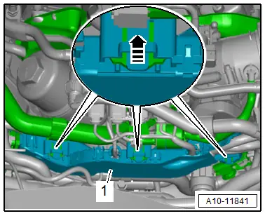
- Release the retainers in direction of -arrow- and remove wiring duct -1- toward the rear.
- Push the wiring duct downward.
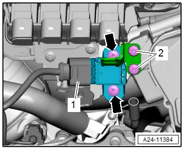
- Remove the Crankcase Ventilation Shut-Off Valve -N548- from the bracket and move it to the side.
- Remove the bolts -2-, and remove the bracket for the Crankcase Ventilation Shut-Off Valve -N548-.
- Remove the bolts -arrows- and remove the Intake Air Temperature Sensor -G42-/Manifold Absolute Pressure Sensor - G71-.
Installing
Install in reverse order of removal and note the following:
 Note
Note
Replace the O-rings after removing them.
- Connections and wire routing. Refer to → Wiring diagrams, Troubleshooting & Component locations.
- Install the engine cover. Refer to → Chapter "Engine Cover, Removing and Installing".
Tightening Specifications
- Refer to → Chapter "Overview - Supercharger"
Fuel Pressure Sensor -G247-, Removing and Installing
Special tools and workshop equipment required
- Elbow Assembly Tool -T10118-
- Socket - 27mm -T40218- or 27 mm socket, commercially available
Removing
- Remove the supercharger. Refer to → Chapter "Supercharger, Removing and Installing".
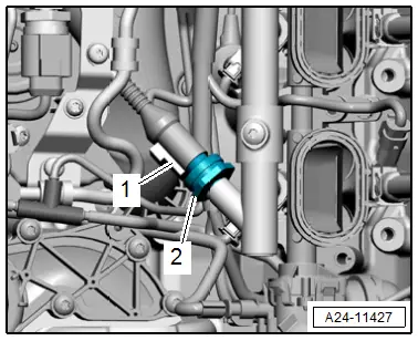
- Disconnect the connector -1-.
 WARNING
The fuel system is under pressure.
Risk of injury from fuel spraying out.
- Wear protective eyewear.
- Wear safety gloves.
- Reduce the pressure: place clean cloths around the connection point and carefully open the connection point.
- Remove the Fuel Pressure Sensor -G247--2-.
Installing
Install in reverse order of removal and note the following:
- Before tightening the fuel pressure sensor check the connection tightening specification.
- Install the supercharger. Refer to → Chapter "Supercharger, Removing and Installing".
Tightening Specifications
- Refer to → Chapter "Overview - Fuel Rail with Fuel Injectors"
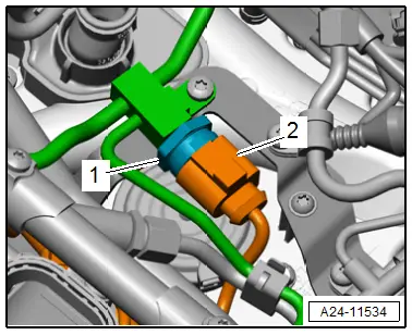
Low Fuel Pressure Sensor -G410-, Removing and Installing
Removing
- Remove the supercharger. Refer to → Chapter "Supercharger, Removing and Installing".
- Disconnect the connector -2-.
 WARNING
The fuel system is under pressure.
Risk of injury from fuel spraying out.
- Wear protective eyewear.
- Wear safety gloves.
- Reduce the pressure: place clean cloths around the connection point and carefully open the connection point.
- Remove the Low Fuel Pressure Sensor -G410--1-.
Installing
Install in reverse order of removal and note the following:
- Install the supercharger. Refer to → Chapter "Supercharger, Removing and Installing".
Tightening Specifications
- Refer to → Chapter "Overview - Intake Manifold Lower Section with Fuel Rail"

