Audi Q7: Trailer Hitch
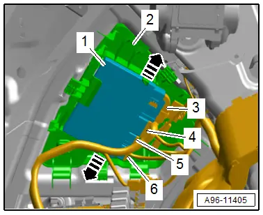
Component Location Overview - Trailer Hitch
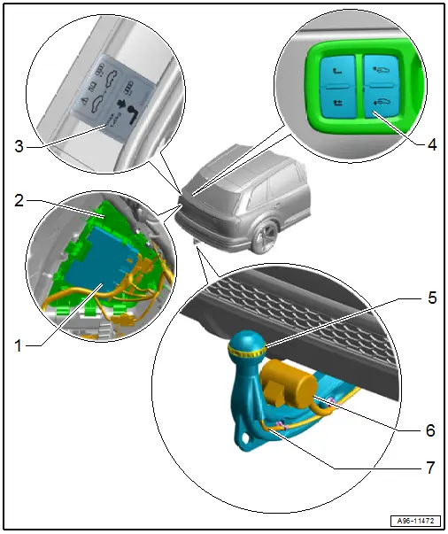
1 - Towing Recognition Control Module -J345-
- Overview. Refer to → Chapter "Overview - Trailer Hitch".
- Removing and Installing. Refer to → Chapter "Towing Recognition Control Module -J345-, Removing and Installing".
2 - Frame
- For Towing Recognition Control Module -J345-
3 - Information Label
- On the left side of the body at the rear
4 - Power Pivoting Trailer Hitch Button -E474-
- Component Location Overview. Refer to → Electrical Equipment; Rep. Gr.96; Controls; Component Location Overview - Luggage Compartment Controls
5 - Trailer Hitch Bend Angle Sensor -G820-
- Overview. Refer to → Chapter "Overview - Trailer Hitch".
- Removing and Installing. Refer to → Chapter "Trailer Hitch Bend Angle Sensor -G820-, Removing and Installing".
6 - Trailer Socket -U10-
- Overview. Refer to → Chapter "Overview - Trailer Hitch".
- Removing and installing. Refer to → Electrical Equipment General Information; Rep. Gr.96; Trailer Hitch.
7 - Connector
- For Trailer Hitch Bend Angle Sensor -G820-
Overview - Trailer Hitch
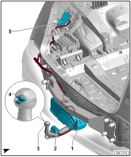
1 - Trailer Hitch
- Component Location Overview. Refer to → Chapter "Component Location Overview - Trailer Hitch".
- Only removable with the impact member
- Removing and Installing. Refer to → Chapter "Impact Member, Removing and Installing, Vehicles with Trailer Hitch".
2 - Trailer Socket -U10-
- Removing and installing. Refer to → Electrical Equipment General Information; Rep. Gr.96; Trailer Hitch.
3 - Ring on Trailer Hitch Bend Angle Sensor -G820-
- Removing and Installing. Refer to → Chapter "Trailer Hitch Bend Angle Sensor -G820-, Removing and Installing".
4 - Trailer Hitch Bend Angle Sensor -G820-
- Removing and Installing. Refer to → Chapter "Trailer Hitch Bend Angle Sensor -G820-, Removing and Installing".
5 - Towing Recognition Control Module -J345-
- Removing and Installing. Refer to → Chapter "Towing Recognition Control Module -J345-, Removing and Installing".
Trailer Hitch Bend Angle Sensor -G820-, Removing and Installing
Ring on Trailer Hitch Bend Angle Sensor -G820-, Removing and Installing
Removing
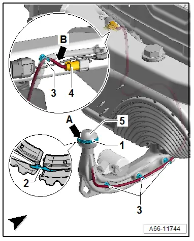
- Push the ring covering -1- at the separating point -arrow A- to the side and release the locking mechanism -2-.
- Open the ring at the separating point -arrow A- and remove it from the ball head -5-.
Installing
Install in reverse order of removal and note the following:
- The smaller ring diameter must face upward.
- The ring locking mechanism must engage audibly.
Trailer Hitch Bend Angle Sensor -G820-, Removing and Installing
Removing
- Remove the ring on Trailer Hitch Bend Angle Sensor -G820-.
- Disconnect the cable tie -3- along the connector -4-.
- Disconnect the connector -4- and disconnect the wires near the housing -arrow B-.

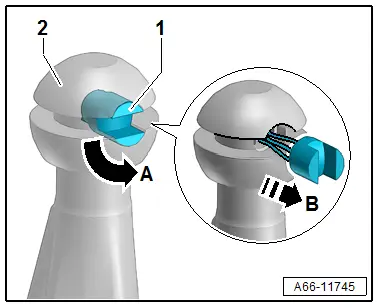
- Turn the bend angle sensor -1- 90º -arrow A- and pull it with the wire out of the ball head -2- for the trailer hitch -arrow B-.
Installing
Install in reverse order of removal and note the following:
- The bend angle sensor must rest flush with the ball head.
- Crimp the wires. Refer to → Electrical System General Information; Rep. Gr.97; Wiring Harness and Connectors, Repairing.
Connector Assignment on Connector Housing for Trailer Hitch Bend Angle Sensor -G820-
- Pin 1: red
- Pin 2: black
- Pin 3: yellow
Towing Recognition Control Module -J345-, Removing and Installing
Removing
- Remove the luggage compartment left trim panel. Refer to → Body Interior; Rep. Gr.70; Luggage Compartment Trim Panels; Luggage Compartment Side Trim Panel, Removing and Installing.
- Release the retainers -arrows- and remove the towing recognition control module -1- from the frame -2-.
- Disconnect the connectors -3 through 6-.
Installing
Install in reverse order of removal and note the following:
- If the control module is being replaced, the "Replace control module" function for the respective control module must be selected. Use the → Vehicle diagnostic tester, Diagnose.
Special Tools
Special tools and workshop equipment required
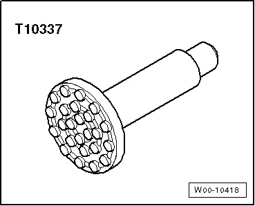
- Engine/Gearbox Jack - Gearbox Support -T10337-
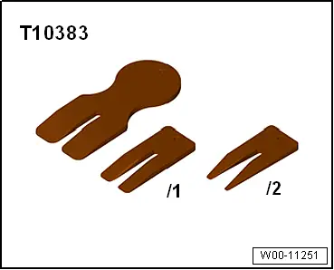
- Wedge Set -T10383-
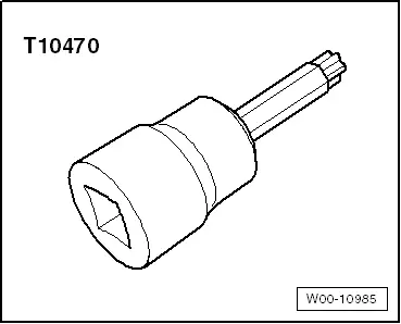
- Socket - Torx T50 -T10470-
- Double Suction Lifter -VAG1344-
- Wiring Harness Repair Set - Hot Air Blower -VAS1978/14A-
- Container of the Coolant Collection System -VAS5014- or the Shop Crane - Drip Tray -VAS6208-
- Engine Bung Set -VAS6122-
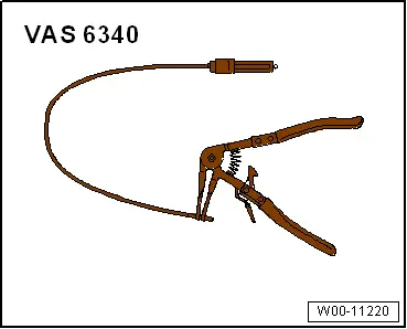
- Hose Clip Pliers -VAS6340-
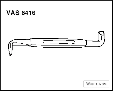
- Angled Screwdriver -VAS6416-
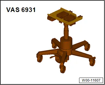
- Engine and Gearbox Jack -VAS6931-
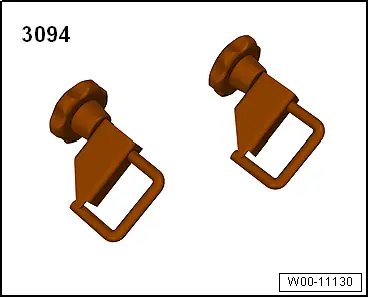
- Hose Clamps - Up To 25 mm -3094-
- Roller -3356-
- Trim Removal Wedge -3409-
- Hand drill
- 5 mm drill bit
Revision History
DRUCK NUMBER: A005A011121