Audi Q7: Vacuum System
Overview - Vacuum Pump
Overview - Vacuum Pump, 3.0L TFSI Engine
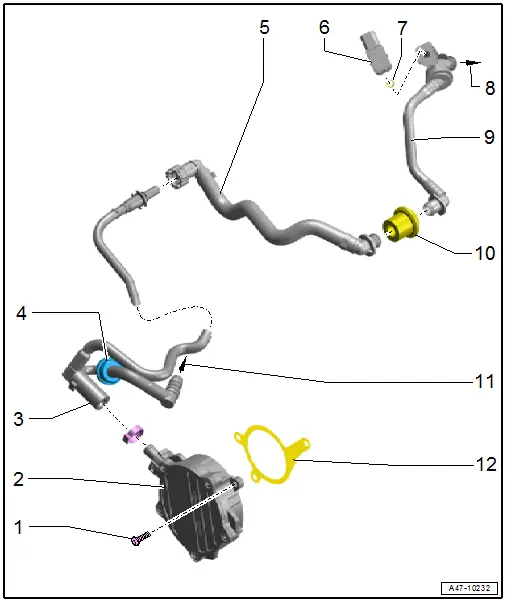
1 - Bolt
- 9 Nm
2 - Vacuum Pump
- Refer to → Chapter "Vacuum Pump, Removing and Installing, 3.0L TFSI Engine"
3 - Vacuum Line
4 - Check Valve
- Cannot be replaced separately
- Refer to → Chapter "Check Valve, Checking"
5 - Vacuum Line
- Refer to → Chapter "Check Valve with Vacuum Hose in Engine Compartment, Removing and Installing, 3.0L TDI Engine"
6 - Brake Booster Pressure Sensor -G294-
- Refer to → Chapter "Brake Booster Pressure Sensor, Removing and Installing"
7 - O-Ring
- Cannot be replaced separately
- If damaged, replace the Brake Booster Pressure Sensor -G294-
8 - To the Brake Booster
9 - Vacuum Line
- With integrated check valve
- Refer to → Chapter "Check Valve, Checking"
- The check valve cannot be replaced separately
10 - Grommet
11 - To the Solenoid Valve
12 - Seal
- Replace after removing
Check Valve, Checking
- Remove the check valve. Refer to → Chapter "Check Valve, Removing and Installing".
- The valve must allow air to flow in the direction of the vacuum pump.
- Valve must remain closed in the direction of the brake booster.
- Install the check valve. Refer to → Chapter "Check Valve, Removing and Installing".
 Note
Note
Note the flow direction: the arrow symbol faces the vacuum pump.
Check Valve, Removing and Installing
Check Valve with Vacuum Hose in Plenum Chamber, Removing and Installing, 3.0L TFSI Engine
 Note
Note
The check valve is integrated in the vacuum hose and cannot be replaced separately.
Removing
- Remove the plenum chamber cover. Refer to → Body Exterior; Rep. Gr.50; Bulkhead; Plenum Chamber Cover, Removing and Installing.
 Caution
Risk of damaging the vacuum hoses.
Carefully remove the vacuum hoses. Replace the vacuum hose if damaged.
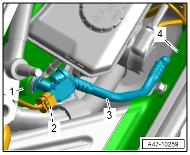
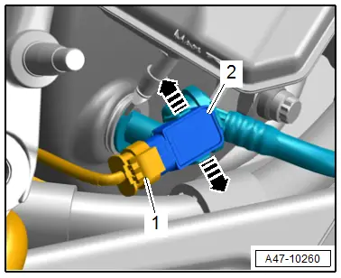
- Disconnect the connector -2- for the Brake Booster Pressure Sensor -G294-.
- Carefully remove the vacuum hose -3- from the plenum chamber bulkhead -4- and from the brake booster -1-.
Installing
Install in reverse order of removal and note the following:
 Note
Note
Coating the vacuum hose with water (not with oil) makes it easier to remove.
- Install the plenum chamber cover. Refer to → Body Exterior; Rep. Gr.50; Bulkhead; Plenum Chamber Cover, Removing and Installing.
Vacuum Pump, Removing and Installing
Vacuum Pump, Removing and Installing, 3.0L TFSI Engine
Special tools and workshop equipment required
- Hose Clip Pliers -VAG1275A-
- Torque Wrench 1331 5-50Nm -VAG1331-
 Caution
This procedure contains mandatory replaceable parts. Refer to component overview prior to starting procedure.
Mandatory Replacement Parts
- Seal - Vacuum Pump
Removing
- Remove the engine cover. Refer to → Rep. Gr.10; Engine Cover; Engine Cover, Removing and Installing.
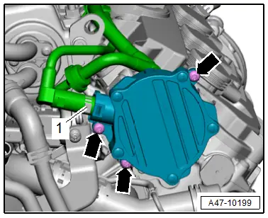
- Loosen the hose clamp -1- and remove the vacuum hose.
- Remove the bolts -arrows- and remove the vacuum pump.
Installing
Install in reverse order of removal and note the following:
 Note
Note
- Replace the seal after removal.
- Secure all hose connections with hose clamps that match the ones used in series production. Refer to the Parts Catalog.
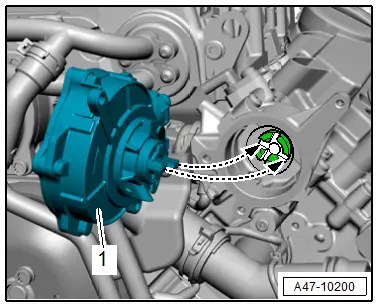
- Position the vacuum pump driver -1- so it engages in the symmetrical groove on the camshaft when positioning -arrows-.
- Install the vacuum hose with the hose clamp -1- connected.
- Install the engine cover. Refer to → Rep. Gr.10; Engine Cover; Engine Cover, Removing and Installing.

Tightening Specifications
- Refer to → Chapter "Overview - Vacuum Pump"
Vacuum Pump, Removing and Installing, 3.0L TDI Engine
The vacuum pump and oil pump are combined in one unit.
Removing and installing. Refer to → Rep. Gr.17; Oil Pan/Oil Pump; Oil Pump, Removing and Installing.
Brake Booster Pressure Sensor, Removing and Installing
Removing
- Remove the plenum chamber cover. Refer to → Body Exterior; Rep. Gr.50; Bulkhead; Plenum Chamber Cover, Removing and Installing.
- Disconnect the connector -1- for the Brake Booster Pressure Sensor -G294-.
- Release the catches -arrows- and carefully remove the Brake Booster Pressure Sensor -G294--2-.
Installing
Install in reverse order of removal and note the following:
- Install the plenum chamber cover. Refer to → Body Exterior; Rep. Gr.50; Bulkhead; Plenum Chamber Cover, Removing and Installing.

