Audi Q7: Air Filter
Overview - Air Filter Housing
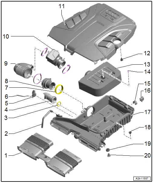
1 - Air Duct
- On the lock carrier
- Remove any dirt, leaves and salt residue.
2 - Water Drain Hose
- Clean
3 - O-Ring
- Replace after removing
4 - Secondary Air Injection Hose
- For removal, press the release buttons on both sides
5 - Air Filter Bypass Door Valve -N275-
6 - Vacuum Hose
- From the Air Filter Bypass Door Valve -N275- to the air filter bypass door
7 - Gasket
- Replace if damaged
8 - Connection
9 - Air Duct Pipe
- Clamp tightening specification. Refer to → Chapter "Overview - Charge Air Hose Connections".
10 - Resonator
11 - Air Filter Upper Section
- Clean off any salt and dirt
- Removing and installing. Refer to → Chapter "Air Filter Housing, Removing and Installing".
12 - Grommet
13 - Air Filter Element
- Use an original air filter element. Refer to the Parts Catalog.
- Replacement intervals. Refer to the Maintenance Tables
- Removing and installing.
14 - Bolt
- 3.5 Nm
15 - Stop Buffer
- Replace if damaged
16 - Mount
- For the air filter housing
17 - Air Filter Lower Section
- Remove any dirt, leaves and salt residue.
- Removing and installing. Refer to → Chapter "Air Filter Housing, Removing and Installing".
18 - Grommet
19 - Grommet
20 - Mount
- For the air filter housing
Air Filter Housing, Removing and Installing
Removing
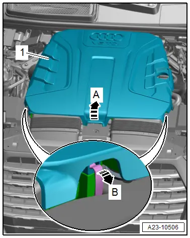
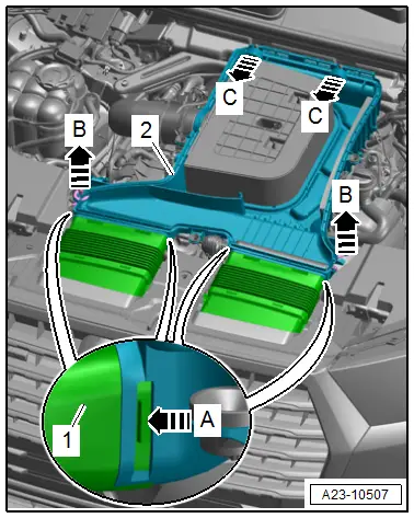
- Open the left and right clip in direction of -arrow B-.
- Remove the air filter upper section -1- in the center toward the rear from the ball pins in direction of -arrow A- and disengage from the air filter lower section.
- Remove the air filter upper section.
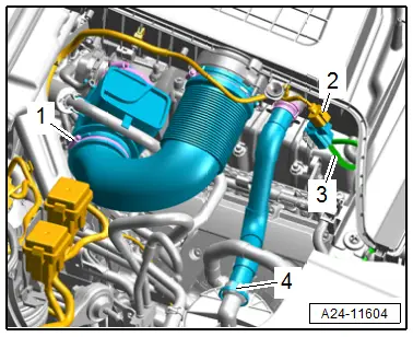
- Loosen the hose clamp -1- and remove the air duct pipe.
- Remove the secondary air injection hose -4- by pressing the catches on both sides.
- Disconnect the connector -2- for the Air Filter Bypass Door Valve -N275-.
- Remove the vacuum hose -3-.
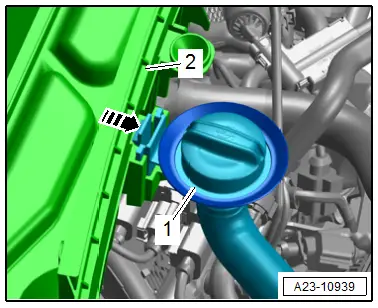
- Release the retainer in direction of -arrow- and oil filler tube -1- upward from the air filter lower section -2-.
- Release the retainer in direction of -arrow A- and remove the air ducts -1- from the air filter lower section -2-.
- Remove the front air filter lower section from the ball pin upward in direction of -B arrows- and then remove the rear mount toward the front in direction of -C arrows-.
Installing
 Note
Note
- The air filter housing must always be clean.
- To avoid malfunctions, the critical airflow components such as the mass airflow sensor, air duct pipes, etc. must be covered with a clean cloth when blowing out the air filter housing with compressed air.
- The hose connections as well as air duct pipes and hoses must be free of oil and grease before installing.
- Use a silicone-free lubricant for installing the air duct hoses.
- Replace the O-ring after removing.
- Secure all hose connections with hose clamps that match the ones used in series production. Refer to the Parts Catalog.
- Check the air duct pipe (intake air side) for salt residue, dirt and leaves.
- Check the air duct from the lock carrier to the air filter housing for dirt and leaves.
Install in reverse order of removal and note the following:
- Connections and wire routing. Refer to → Wiring diagrams, Troubleshooting & Component locations.
Tightening Specifications
- Refer to → Chapter "Overview - Air Filter Housing"
- Refer to → Chapter "Overview - Charge Air Hose Connections"

