Audi Q7: ATF
ATF Level, Checking
ATF Level, Checking, 0D3 "Sport Differential"
 Caution
This procedure contains mandatory replaceable parts. Refer to component overview prior to starting procedure.
Mandatory Replacement Parts
- Plug - ATF check
Test Requirement
- ATF temperature: 10 ºC to 60 ºC (50 to 140 ºF)
- The rear final drive must be in the installed position.
- The vehicle must be level.
- Refer to → Chapter "Component Location Overview - Drain and Check Plugs, 0D3 Sport Differential"
Special tools and workshop equipment required
- Drip Tray
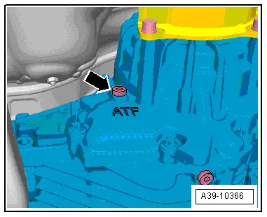
- Remove the ATF check plug -1- to check the ATF level.
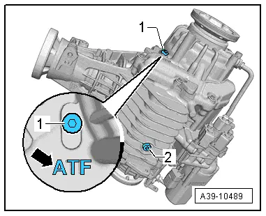
Tip:
- The ATF check plug -1- is located on the left side of the rear final drive. Identification "ATF" on the final drive housing -arrow-
- ATF plug overview. Refer to → Chapter "Component Location Overview - Drain and Check Plugs, 0D3 Sport Differential".
- The ATF level is correct when the rear final drive is filled to the lower edge of the fill hole.
If the ATF is correct:
- Install the new ATF check plug and fasten. Tightening specification. Refer to → Fig. "ATF Drain Plugs on Rear Final Drive 0D3".
If the ATF is not correct:
- Fill the ATF. Refer to → Chapter "ATF, Filling, 0D3 Sport Differential".
ATF, Draining and Filling
ATF, Draining, 0D3 "Sport Differential"
Special tools and workshop equipment required
- Drip Tray
 Caution
This procedure contains mandatory replaceable parts. Refer to component overview prior to starting procedure.
Mandatory Replacement Parts
- Plug - ATF drain
- Plug - ATF check
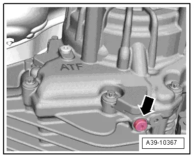
- Remove the ATF check plug -arrow- so that the ATF drains faster.

- Remove the ATF drain plug -arrow- and drain the ATF.
- Install the new ATF drain plug -arrow- and tighten. Tightening specification. Refer to → Fig. "ATF Drain Plugs on Rear Final Drive 0D3".
- Fill the ATF in the rear final drive. Refer to → Chapter "ATF, Filling, 0D3 Sport Differential".
ATF, Filling, 0D3 "Sport Differential"
Special tools and workshop equipment required
- Vehicle Diagnostic Tester
- Charging Device For Haldex Coupling 2 -VAS6291- or Charging Device For Haldex Coupling 2 -VAS6291A-
- Charging Device For Haldex Coupling 2 - Adapter 3 -VAS6291/3-
- Drip Tray
 Caution
This procedure contains mandatory replaceable parts. Refer to component overview prior to starting procedure.
Mandatory Replacement Parts
- Plug - ATF check
Test Conditions:
- The rear final drive must be in the installed position.
- The vehicle must be level.
- Refer to → Chapter "Component Location Overview - Drain and Check Plugs, 0D3 Sport Differential"
- The ATF drain plug is installed and tightened. Tightening specification. Refer to → Fig. "ATF Drain Plugs on Rear Final Drive 0D3".
 NOTICE
Using incorrect transmission fluid.
Risk of damaging the transmission.
- Only use transmission fluid as specified in the Parts Catalog.
- Use the -VAS6291A- to fill.
- The ATF filler tool must be clean and the ATF must not be mixed with any other oils.
- Lift the vehicle.
- Remove the ATF check plug -1-.
Tip:
- The ATF check plug -1- is located on the left side of the rear final drive. Identification "ATF" on the final drive housing -arrow-

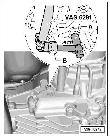
- Disconnect the adapter -A- and elbow -B-.
- Install in the adapter -A- all the way.
- Attach the elbow -B- to the adapter -A-.
- Route the hose over the left drive axle.
- The hose must not sag. It must be routed over the left rear wheel on the vehicle.
- Lower the vehicle.
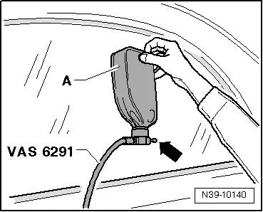
- Make sure that the valve -arrow- is closed.
- Install the oil container -A- on the -VAS6291A-.
- Open the valve -arrow- and hold the oil container as shown.
The hydraulic control unit and the left and right chambers in the rear final drive are now filled.
- When the correct filling of the rear final drive hydraulic control module ATF drips from the adapter -A-
If there still is no ATF in the adapter -A-:
- Continue filling until the level is correct.
When ATF starts to leak out of the adapter -A-:
- Lift the vehicle.
- Place the oil container for example on a tool box.
A portion of the excess oil runs back into the oil container.
- If no more ATF runs back, remove the -VAS6291A-.
- The oil level is correct when the rear final drive is filled up to the lower edge of the oil fill hole.

- Install the ATF check plug -arrow- hand-tight.
- Connect the Vehicle Diagnostic Tester and turn on the ignition.
- Select the function 22 - AWD Electronics in the Vehicle Diagnostic Tester under Guided Functions in the directory 22- ATF Filling.
- Follow all the instructions given by the Vehicle Diagnostic Tester exactly.
The system is filled and bled using the Vehicle Diagnostic Tester.
Tip:
- Repeat the filling process if the system detects there is still air inside the system after performing the 22 - ATF Filling function.
- Remove the ATF check plug -arrow- again.
Test Condition:
- The ATF level is correct when the rear final drive is filled up to the lower edge of the filler hole -arrow-.
- If necessary fill the ATF.
- In the DTC memory there is no entry and no "sporadic malfunction". Refer to Vehicle Diagnostic Tester.
- Install the new ATF check plug -arrow- and tighten. Tightening specification. Refer to → Fig. "ATF Drain Plugs on Rear Final Drive 0D3".

