Audi Q7: Left Seal, Replacing
Left Seal, Replacing, 0DB, 0D2
Special tools and workshop equipment required
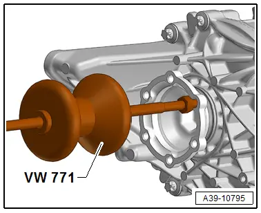
- Slide Hammer Set -VW771-
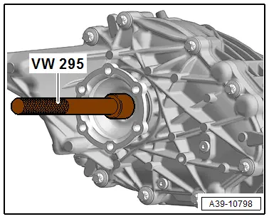
- Bearing/Bushing Installer - Multiple Use -VW295-
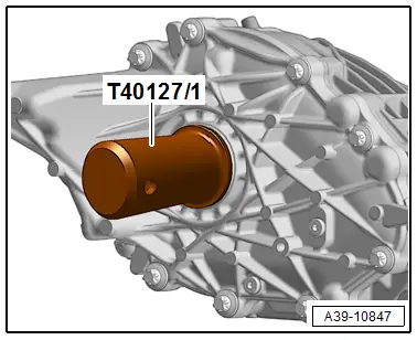
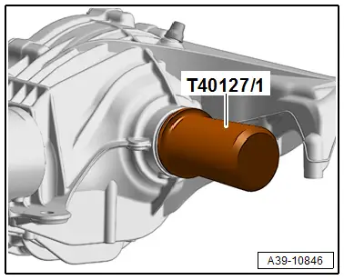
- Seal Installer - Double Radial Oil Seal -T40127/1-
- Sealing Grease -G 052 128 A1-
 Caution
This procedure contains mandatory replaceable parts. Refer to component overview prior to starting procedure.
Mandatory Replacement Parts
- Circlip - Left Flange Shaft to Rear Final Drive
- The rear final drive is removed. Refer to → Chapter "Final Drive, Removing and Installing".
- Follow all general repair information. Refer to → Chapter "Repair Information".
- Drive out the left flange shaft with the Slide Hammer Set -VW771-.
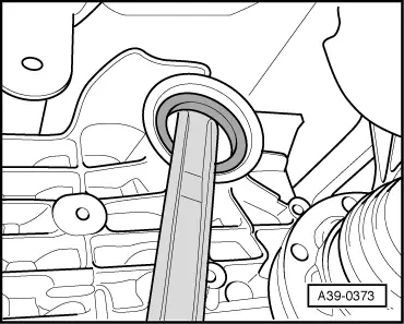
- Use a suitable tool to pry out the seal.
- Coat outer edge of the seal with gear oil.
- Fill the space between the sealing/dust lip halfway with Sealing Grease -G 052 128 A1-.
- Install the new shaft seal with Seal Installer - Double Radial Oil Seal -T40127/1- all the way. Do not the tilt the shaft seal while doing so.
- Clamp the flange shaft in a vise with protective jaws.
- Remove the old circlip.
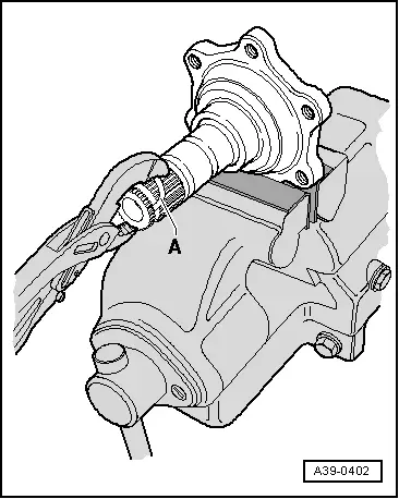
- Insert a new circlip -A- using Pliers in the groove on the flange shaft at the same time do not stretch the circlip.

- Drive the flange shaft in using a - VW295-.
- Install the rear final drive. Refer to → Chapter "Final Drive, Removing and Installing".
- Check the rear final drive gear oil. Refer to → Chapter "Gear Oil, Checking Level".
Right Seal, Replacing
Right Seal, Replacing, 0DB, 0D2
Special tools and workshop equipment required
- Slide Hammer Set -VW771-
- Bearing/Bushing Installer - Multiple Use -VW295-
- Seal Installer - Double Radial Oil Seal -T40127/1-
- Sealing Grease -G 052 128 A1-
 Caution
This procedure contains mandatory replaceable parts. Refer to component overview prior to starting procedure.
Mandatory Replacement Parts
- Circlip - Right Flange Shaft to Rear Final Drive
- The rear final drive is removed. Refer to → Chapter "Final Drive, Removing and Installing".
- Follow all general repair information. Refer to → Chapter "Repair Information".
- Drive out the left flange shaft with the Slide Hammer Set -VW771-.

- Use a suitable tool to pry out the seal.

- Coat outer edge of the seal with gear oil.
- Fill the space between the sealing/dust lip halfway with Sealing Grease -G 052 128 A1-.
- Install the new shaft seal with -T40127/1- all the way. Do not the tilt the shaft seal while doing so.
- Clamp the flange shaft in a vise with protective jaws.
- Remove the old circlip.
- Insert a new circlip -A- using Pliers in the groove on the flange shaft at the same time do not stretch the circlip.
- Drive the flange shaft in using a - VW295-.
- Install the rear final drive. Refer to → Chapter "Final Drive, Removing and Installing".
- Check the rear final drive gear oil. Refer to → Chapter "Gear Oil, Checking Level".

Input Shaft Seal, Replacing
Input Shaft Seal, Replacing, 0DB, 0D2
Special tools and workshop equipment required
- Puller - Multiple Use -VW391-
- Slide Hammer Set - Adapter 40 - VW771/40- from the Slide Hammer Set - VW771-
- Puller - Unit Injector -T10055-
- Seal Installer - Hollow Shaft -T10380-
- -2-Puller - Unit Injector - Adapter 2 -T10055/2-
- Seal Installer - Input Shaft - Guide Sleeve -T40222/1-
- Inductive Heater -VAS6414-
or
- Commercially Available Hotplate with Digital Thermometer -VAS6519-
- Used Oil Collection and Extraction Unit -SMN372500-
- Sealing Grease -G 052 128 A1-
- Two M 8 x 30 Bolts
 Caution
This procedure contains mandatory replaceable parts. Refer to component overview prior to starting procedure.
Mandatory Replacement Parts
- Circlip for Flange/Driveshaft
Removing
- The rear final drive is removed.
- Pay attention to the general repair information. Refer to → Chapter "Repair Information".
- Place the vehicle on a hoist.
Audi Q7
- Remove the center underbody trim panel. Refer to → Body Exterior; Rep. Gr.66; Underbody Trim Panel; Underbody Trim Panels, Removing and Installing.
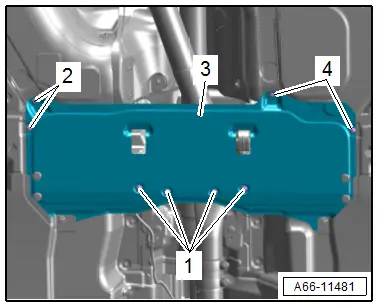
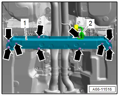
- Remove the bolts -arrows- and the crossmember -1-.
 NOTICE
Incorrect handling can damage the coupling.
- Do not bend the coupling more than 10º.
- Do not load the coupling.
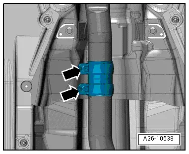
- Loosen the lock washer(s) -arrows- and separate the exhaust system.
- Tie up the front exhaust pipe(s) on the side to the underbody.
Audi A4
- Remove the rear section of the exhaust system. Refer to → Rep. Gr.26; Exhaust Pipes/Mufflers; Overview - Muffler.
Continuation for All Vehicles
- Remove the driveshaft on the rear final drive. Refer to → Chapter "Drive Shaft, Removing from Rear Final Drive and Installing".
- Tie the driveshaft to the side.
- Remove the High Temperature Grease in the flange/driveshaft.
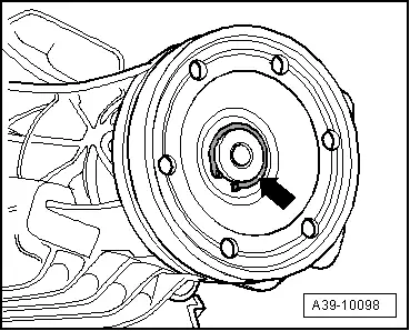
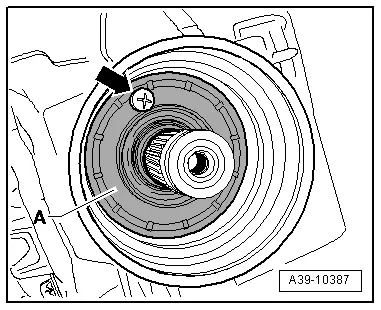
- Remove the circlip -arrow-.
- Replace the circlip with a new one of the same thickness if it is stretched or damaged. Allocation. Refer to the Parts Catalog.
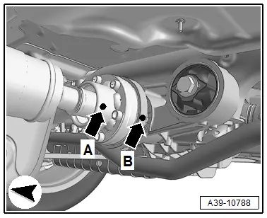
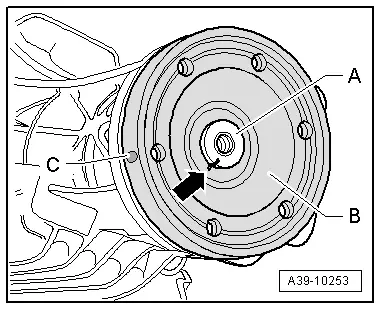
- Mark the position of the flange/driveshaft -B- on the pinion -A--arrow-.
- This marking -arrow- is needed so the colored dot -C- on the outer flange remains in its original position.
- This ensures the imbalance in the rear final drive will be as small as possible.

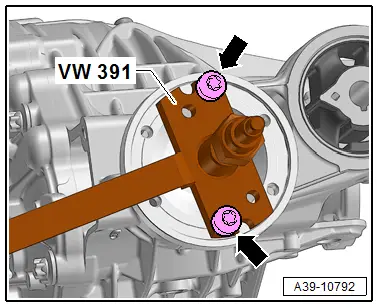
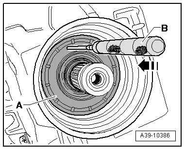
- Secure the -VW391- with Two M 8 x 30 Bolts-arrow- on the flange/driveshaft.
- Remove the flange/driveshaft with the - VW391-.
- Place the -SMN372500- underneath.
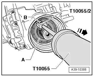
- Knock through the metal ledge of the shaft seal -A-, for example, with a scriber -B- in the direction of -arrow-.
- Then install a bolt -arrow- in this shaft seal opening -A-.
- Remove the shaft seal -A- for the flange/driveshaft over the bolt -B- in the direction of -arrow-.
Installing
Install in reverse order of removal. Note the following:
- Fill the space between the sealing/dust lip halfway with Sealing Grease -G 052 128 A1-.
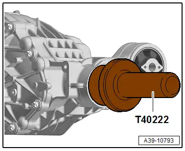
- Place the new shaft seal -A- on the -T40222/1-.
Tip:
- Make sure the shaft seal spring is in its installation position behind the sealing lip.
- Coat outer edge of the seal with gear oil.
- Push the -T40222/1- and the shaft seal -A- onto the pinion -B-.
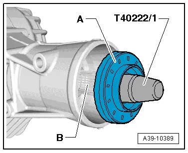
- Push in the new shaft seal to the "installation dimension" using the -T40222-.
Seal Installation Dimension on Final Drive 0DB:
- 25.5 mm +- 0.3 under housing outer edge
Seal Installation Dimension on Final Drive 0D2:
- 24.0 mm +- 0.3 under housing outer edge
- Remove the -T40222- and -T40222/1-.
 CAUTION
Hot components.
Burning of hands is possible.
- Wear safety gloves.
- If using a Heating Plate the temperature must be observed using a -VAS6519-.
- Warm the flange/driveshaft -B- with a -VAS6414- or a Heating Plate to 115 ºC (239 ºF).
- Position the flange/driveshaft -B- on the pinion -A- so that the mark -arrow- is in a straight line.
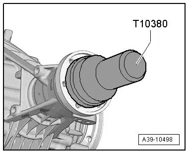
- Install the flange/driveshaft with the -T10380-.
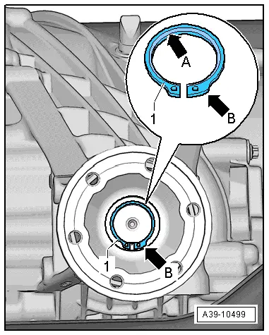
Install the circlip -1- as follows:
- Always replace the circlip -1-.
- The bevel on the inner diameter of the circlip -arrow A- faces out, toward the driveshaft.
- The wide tab on the circlip -arrow B- must be on the right side, as shown.
Note the following When Replacing the Flange/Driveshaft
- The locking ring -1- must be determined again.
- For this, determine and insert the thickest locking ring -1- that can still be installed in the groove. Refer to the Parts Catalog for the part number.
- Attach the driveshaft to the rear final drive. Refer to → Fig. "Install the Driveshaft on the Rear Final Drive.".
- Check the rear final drive gear oil. Refer to → Chapter "Gear Oil, Checking Level".
- Install the crossmember. Refer to → Body Exterior; Rep. Gr.66; Underbody Trim Panel; Overview - Underbody Trim Panels.
- Assemble the exhaust system. Refer to → Rep. Gr.26; Exhaust Pipes/Mufflers; Overview - Muffler.


