Audi Q7: Brake Booster/Brake Master Cylinder
Overview - Brake Booster/Brake Master Cylinder
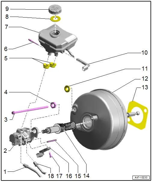
1 - Brake Line
- 14 Nm
- Brake master cylinder/secondary piston circuit to hydraulic unit
2 - Master Brake Cylinder
- Replace completely if faulty
- Refer to → Chapter "Brake Master Cylinder, Removing and Installing"
3 - Bolt
- 23 Nm
4 - Nut
- 23 Nm
- Replace after removing
5 - Plugs
- To install, coat with brake fluid
6 - Locking Pin
- Slide through the brake fluid reservoir and the master brake cylinder
- The locking pin must be pushed into the brake fluid reservoir tab.
7 - Brake Fluid Reservoir
- Refer to → Chapter "Brake Fluid Reservoir, Removing and Installing"
8 - Seal
- Replace if damaged
9 - Cap
10 - Brake Fluid Level Warning Switch -F34-
- Refer to → Chapter "Brake Fluid Level Warning Switch -F34-, Removing and Installing"
11 - Gasket
- Replace after removing
12 - Brake Booster
- Function Test:
- With the engine switched off, depress the brake pedal firmly several times (to reduce the vacuum in the device).
- Hold the brake pedal with average foot pressure and start the engine. If the brake booster is working properly, the brake pedal will be felt to give noticeably under foot (booster becomes effective).
- Refer to → Chapter "Brake Booster, Removing and Installing"
- Adjusting ball head. Refer to → Fig. "Brake Booster Ball Head, Adjusting".
13 - Seal
- Replace after removing
14 - Push Rod
The push rod is only loosely pressed in the brake master cylinder and can when fall out when the brake booster is removed.
15 - Actuator Pin
- For the Brake Lamp Switch -F-
- Must not fall in the brake booster when removing the brake master cylinder.
- Must remain inserted when installing the brake master cylinder
- Refer to → Chapter "Note"
16 - Brake Lamp Switch -F-
- Refer to → Chapter "Brake Lamp Switch, Removing and Installing"
17 - Bolt
- 8 Nm
18 - Brake Line
- 14 Nm
- Brake master cylinder/primary piston circuit to hydraulic unit
Brake Booster Ball Head, Adjusting
- Dimension -a- = 164.7 mm +- 0.5 mm
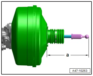
 Note
Note
- Surface -1- for measuring.
- When measuring, ball head must be arranged at a right angle to the surface of the brake booster.
- Measure to end of ball head without gasket installed.
Tightening Specification
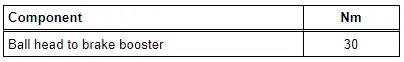
Note
The actuator pin must always be pushed in the hole in the brake master cylinder directly on the Brake Lamp Switch -F-.
Do not bend the actuator pin.
If this pin is missing or is damaged, the brake lamp will not function.
The actuator pin only functions for the brake lamp not for the brake system.
The actuator pin cannot be replaced separately.
Brake Booster, Removing and Installing
Special tools and workshop equipment required
- Torque Wrench 1331 5-50Nm -VAG1331-
- M10 plug -1- or M12 -2- from the Assembly Part Set -5Q0 698 311-
 Caution
This procedure contains mandatory replaceable parts. Refer to component overview prior to starting procedure.
Mandatory Replacement Parts
- Seal - Brake Booster
- Gasket - Brake Booster
Removing
- Switch off the ignition.
- Remove the vacuum in the brake booster by pressing the brake pedal repeatedly.
- Disconnect the brake pedal from the brake booster. Refer to → Chapter "Brake Pedal, Disconnecting from Brake Booster".
- Remove the additional reinforcement for the tower brace. Refer to → Suspension, Wheels, Steering; Rep. Gr.40; Suspension Strut and Upper Control Arm; Tower Brace, Removing and Installing.
- Remove the brake fluid reservoir. Refer to → Chapter "Brake Fluid Reservoir, Removing and Installing".
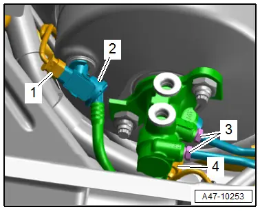
- Disconnect the connector -1- on the Brake Booster Pressure Sensor -G294- and on the Brake Lamp Switch -F--4-.
 Caution
Risk of damaging the vacuum hoses.
Carefully remove the vacuum hoses. Replace the vacuum hose if damaged.
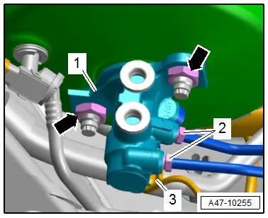
- Disconnect and remove the vacuum hose -1- from the brake booster.
- To protect against escaping brake fluid, place enough lint-free cloths in the area below the brake booster.
- Remove the union bolts -3- for the brake lines, the brake lines from the brake master cylinder and move them slightly to the side.
 Note
Note
Do not change the shape of the brake lines.
- Immediately seal the open connection points with clean plugs from the Assembly Part Set -5Q0 698 311-.
- Remove the bolts -arrows- and carefully remove the brake booster with the brake master cylinder.
 Caution
When removing and installing from the brake master cylinder pay attention that the actuator pin for the brake lamp and the pushrod do not fall into the brake booster.
Installing
 Caution
Always make sure that the actuator pin for the brake lamp is pushed in the brake master cylinder. If this pin is missing the brake lamp will not function.
Install in reverse order of removal and note the following:
 Note
Note
Replace the bolts after removing them.
- Clean the plenum chamber of the remaining escaping brake fluid.
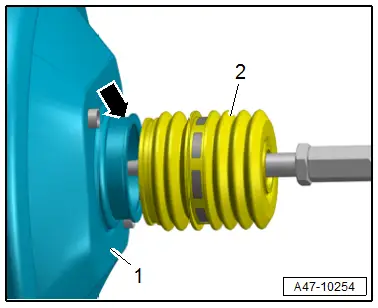
- Check that the boot -2- has not slipped out of the surrounding groove -arrow- on the brake booster -1- as shown.
- Install the brake fluid reservoir. Refer to → Chapter "Brake Fluid Reservoir, Removing and Installing".
- Connect the brake pedal to the brake booster. Refer to → Chapter "Brake Pedal, Disconnecting from Brake Booster".
- Bleed the brake system. Refer to → Chapter "Hydraulic System, Bleeding".
 WARNING
Risk of accident!
- Make sure the brakes are working correctly before driving the vehicle for the first time.
- Ensure that the brake lamp functions correctly.
Tightening Specifications
- Refer to → Chapter "Overview - Brake Booster/Brake Master Cylinder"
- Refer to → Suspension, Wheels, Steering; Rep. Gr.40; Suspension Strut and Upper Control Arm; Overview - Suspension Strut and Upper Control Arm.
Brake Master Cylinder, Removing and Installing
Special tools and workshop equipment required
- Torque Wrench 1331 5-50Nm -VAG1331-
- M10 plug -item 1- or M12 -item 2- from the Assembly Part Set -5Q0 698 311-
 Caution
This procedure contains mandatory replaceable parts. Refer to component overview prior to starting procedure.
Mandatory Replacement Parts
- Nut - Brake Master Cylinder
Removing
- Remove the brake fluid reservoir. Refer to → Chapter "Brake Fluid Reservoir, Removing and Installing".
- Remove the additional reinforcement for the tower brace. Refer to → Suspension, Wheels, Steering; Rep. Gr.40; Suspension Strut and Upper Control Arm; Tower Brace, Removing and Installing.
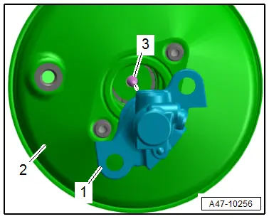
- Disconnect the connector -3- for the Brake Lamp Switch -F-.
 Note
Note
Place a cloth underneath the separating point to catch any escaping brake fluid.
- Remove the union bolts -2- for the brake lines and remove the brake lines from the brake master cylinder -1-.
 Note
Note
Do not change the shape of the brake lines.
- Immediately seal the open connection points with clean plugs from the Assembly Part Set -5Q0 698 311-.
- Remove the nuts -arrows-.
 Caution
Risk of damaging the brake booster.
- When removing the brake master cylinder nothing should fall in the brake booster.
- The piston in the brake master cylinder is not secured.
- The actuator pin for the brake lamp switch must not get lost.
- Disconnect and remove the master brake cylinder from the brake booster.
Installing
Install in reverse order of removal and note the following:
 Note
Note
Replace the seal after removal.
 Caution
Risk of damaging the brake booster.
Do not let any brake fluid run into the brake booster.
There is a risk due to non-functioning brake lamps.
The actuator pin for the brake lamp switch must be inserted in the brake master cylinder.
- When replacing the master brake cylinder -1- pay attention that the pressure rod -3- is seated correctly in the brake booster -2-.
- If necessary: have a second technician slightly press the brake pedal, this allows the brake master cylinder to be guided into pressure rod more easily.
- Install the brake fluid reservoir. Refer to → Chapter "Brake Fluid Reservoir, Removing and Installing".
 WARNING
Risk of accident!
Make sure the brakes are working correctly before driving the vehicle for the first time.
Tightening Specifications
- Refer to → Chapter "Overview - Brake Booster/Brake Master Cylinder"
- Refer to → Suspension, Wheels, Steering; Rep. Gr.40; Suspension Strut and Upper Control Arm; Overview - Suspension Strut and Upper Control Arm.
Brake Fluid Reservoir, Removing and Installing
Special tools and workshop equipment required
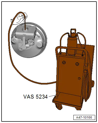
- Brake Charger/Bleeder Unit -VAS5234- with Brake Bleeder Adapter Adapter -VAS5234/1-
- Sealing Tool -T10249-
Removing
- Remove the plenum chamber cover. Refer to → Body Exterior; Rep. Gr.50; Bulkhead; Plenum Chamber Cover, Removing and Installing.
 WARNING
Health Risk.
- Brake fluid is poisonous. NEVER siphon brake fluid by mouth!
- To prevent skin contact with brake fluid, wear chemical resistant safety gloves.
- Follow all disposal regulations.
Malfunctions from contact with brake fluid with fluids containing mineral oils.
Brake fluid must never come into contact with fluids containing mineral oils (oil, gas, cleaning solutions). Safety gloves must be free of oil and grease.
Risk of damaging the painted surfaces.
Due to its caustic nature, brake fluid must also never be brought into contact with paint. Wash off any spilled brake fluid immediately with plenty of water.
- Open the brake fluid reservoir.
- Siphon as much brake fluid as possible using the Brake Charger/Bleeder Unit -VAS5234- with the Brake Bleeder Adapter Adapter -VAS5234/1- from the brake fluid reservoir.
- To protect against escaping brake fluid, place enough lint-free cloths in the area below the brake fluid reservoir.
- Disconnect the connector -2- for the Brake Fluid Level Warning Switch -F34-.
 Note
Note
To protect against escaping brake fluid, place enough lint-free cloths in the area below the master brake cylinder.
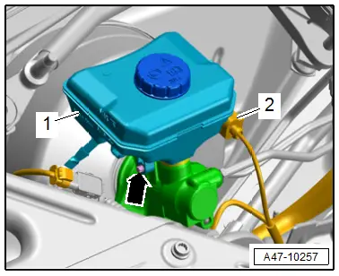
- Remove the bolt -arrow- for the brake fluid reservoir on the side from the brake fluid reservoir and the brake master cylinder.
- Remove the brake fluid reservoir -1- from the plugs.
- Seal the open brake lines and connections immediately with plugs from the Assembly Part Set -5Q0 698 311-.
Installing
 Note
Note
Coat the plugs on the brake fluid reservoir with brake fluid.
- Insert the brake fluid reservoir into the plugs in the brake master cylinder.
Installation is performed in reverse order of removal, while noting the following:
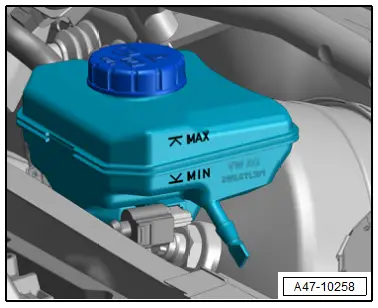
- Fill the brake fluid reservoir to the "MIN" mark.
- Bleed the brake system. Refer to → Chapter "Hydraulic System, Bleeding".
- Install the plenum chamber cover. Refer to → Body Exterior; Rep. Gr.50; Bulkhead; Plenum Chamber Cover, Removing and Installing.
 WARNING
Risk of accident!
Make sure the brakes are working correctly before driving the vehicle for the first time.
Tightening Specifications
- Refer to → Chapter "Overview - Brake Booster/Brake Master Cylinder"
Brake Fluid Level Warning Switch -F34-, Removing and Installing
Removing
- Remove the plenum chamber cover. Refer to → Body Exterior; Rep. Gr.50; Bulkhead; Plenum Chamber Cover, Removing and Installing.
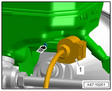
- Disconnect the connector -1-.
- Release the catch in direction of -arrow- and remove the Brake Fluid Level Warning Switch -F34- from the brake fluid reservoir.
Installing
Install in reverse order of removal and note the following:
- Install the plenum chamber cover. Refer to → Body Exterior; Rep. Gr.50; Bulkhead; Plenum Chamber Cover, Removing and Installing.

