Audi Q7: Component Location Overview - Airbag Crash Sensors
Audi Q7 (4M) 2016-2026 Workshop Manual / Body / Body Interior / Passenger Protection, Airbags, Seat Belts / Component Location Overview - Airbag Crash Sensors
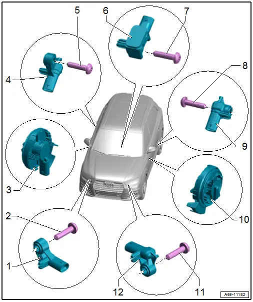
1 - Passenger Side Front Airbag Crash Sensor -G284-
- Component location: on the right side of the headlamp mount
- Removing and installing. Refer to → Chapter "Driver Front Airbag Crash Sensor -G283-, Removing and Installing".
2 - Bolt
- 9 Nm
3 - Front Passenger Thorax Airbag Crash Sensor -G180-
- Component location: inside the door
- For the safety precautions for working with front thorax airbag crash sensors (pressure sensors). Refer to → Chapter "Front Thorax Airbag Crash Sensors (Pressure Sensors) Safety Precautions".
- Removing and installing. Refer to → Chapter "Driver Thorax Airbag Crash Sensor -G179-/ Front Passenger Thorax Airbag Crash Sensor -G180-, Removing and Installing".
- Make sure the seal is seated correctly. Replace crash sensor if damaged or deformed
- The tabs must audibly engage
4 - Passenger Side Rear Thorax Airbag Crash Sensor -G257-
- Behind the sill panel
- Removing and installing. Refer to → Chapter "Driver Side Rear Thorax Airbag Crash Sensor -G256-/ Passenger Side Rear Thorax Airbag Crash Sensor -G257-, Removing and Installing".
5 - Bolt
- 9 Nm
6 - Center Crash Sensor for X/Y Axis -G858-
- Component location: to the rear of the center tunnel under the center console
- Removing and installing. Refer to → Chapter "Driver Side Rear Thorax Airbag Crash Sensor -G256-/ Passenger Side Rear Thorax Airbag Crash Sensor -G257-, Removing and Installing".
7 - Bolt
- 9 Nm
8 - Bolt
- 9 Nm
9 - Driver Side Rear Thorax Airbag Crash Sensor -G256-
- Behind the sill panel
- Removing and installing. Refer to → Chapter "Driver Side Rear Thorax Airbag Crash Sensor -G256-/ Passenger Side Rear Thorax Airbag Crash Sensor -G257-, Removing and Installing".
10 - Driver Thorax Airbag Crash Sensor -G179-
- Component location: inside the door
- For the safety precautions for working with front thorax airbag crash sensors (pressure sensors). Refer to → Chapter "Front Thorax Airbag Crash Sensors (Pressure Sensors) Safety Precautions".
- Removing and installing. Refer to → Chapter "Driver Thorax Airbag Crash Sensor -G179-/ Front Passenger Thorax Airbag Crash Sensor -G180-, Removing and Installing".
- Make sure the seal is seated correctly. Replace crash sensor if damaged or deformed
- The tabs must audibly engage
11 - Bolt
- 9 Nm
12 - Driver Front Airbag Crash Sensor -G283-
- Component location: on the left side of the headlamp mount
- Removing and installing. Refer to → Chapter "Driver Front Airbag Crash Sensor -G283-, Removing and Installing".

