Audi Q7: Engine and Transmission, Separating
Special tools and workshop equipment required
- Scissor Lift Table - Audi Set -VAS6131/10-
- Scissor Lift Table - A8 Set -VAS6131/11-
- Articulated Joint Support -VAS6131/13-7- from the Scissor Lift Table - Q7 Set - VAS6131/13-
- Hose Clip Pliers -VAS6362-
- Engine Support -T10533-
- Crankshaft Socket -T40058-
![]() Caution
Caution
This procedure contains mandatory replaceable parts. Refer to component overview prior to starting procedure.
Mandatory Replacement Parts
- Nuts- Catalytic converter
Procedure
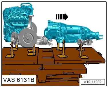
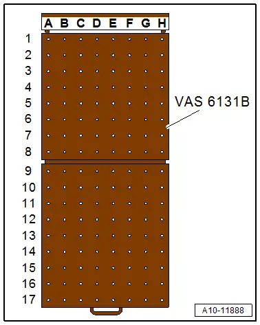
- Engine/transmission assembly removed and placed on the Scissor Lift Table -VAS6131B-.
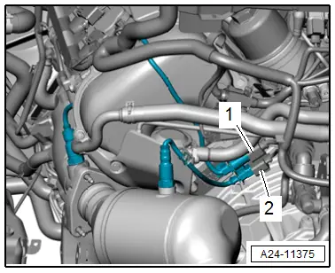
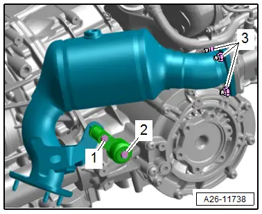
- Remove the connector -2- for the Oxygen Sensor 2 after Catalytic Converter -G131- from the bracket and disconnect it. Free up the wire.
![]() Note
Note
Ignore -1-.
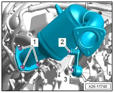
- Remove the nuts -1- and the bolt -3- and then remove the left catalytic converter.
![]() Note
Note
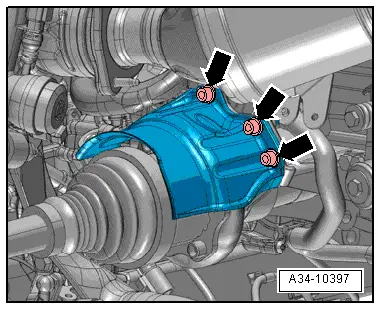
Ignore -2-.
- Remove the connector -1- for the Oxygen Sensor after Three Way Catalytic Converter -G130--2- from the bracket and disconnect it.
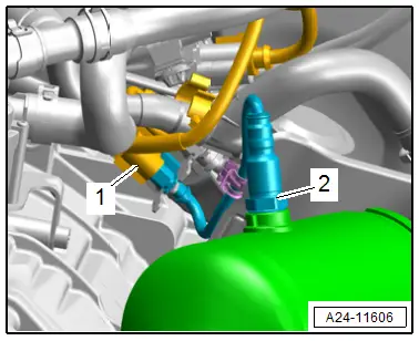
- Remove the nuts -3- and the bolt -2- and remove the right catalytic converter.
![]() Note
Note
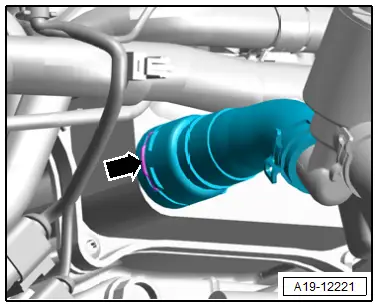
Ignore -1-.
- Lift the clip -arrows- and remove the connection.
- Remove the bolts -arrows- and remove the right drive axle heat shield.
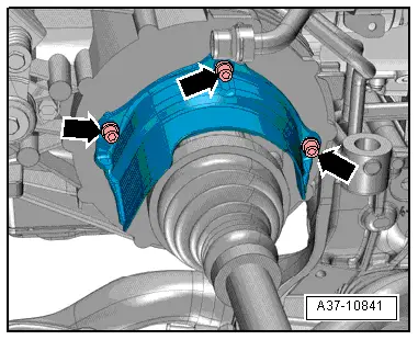
- Remove the bolts -arrows- and remove the left drive axle heat shield.
- Remove the left and right drive axle from the transmission flange shaft. Refer to → Suspension, Wheels, Steering; Rep. Gr.40; Drive Axle; Drive Axle, Removing and Installing.
- Equip the Scissor Lift Table -VAS6131B- with the Scissor Lift Table - Audi Set -VAS6131/10- and Scissor Lift Table - A8 Set -VAS6131/11-, and Scissor Lift Table - Q7 Set Articulated Joint Support -VAS6131/13-7- as follows:
![]() Note
Note
The remaining mounting elements remain unchanged.
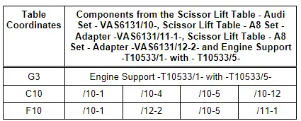
- Tighten the Engine Support -T10533/1- with the -T10533/5- on the front right of the engine as shown.
- Install the engine support on the Scissor Lift Table - VAS6131B- and tighten it to 20 Nm.
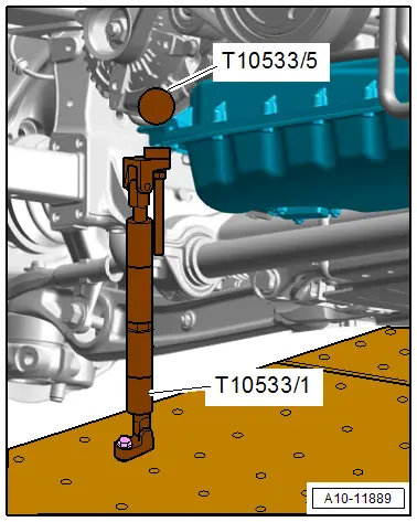
- Attach the mounting elements from the Scissor Lift Table - Audi Set -VAS6131/10- to the transmission on the left as shown.
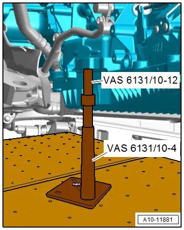
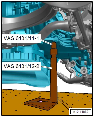
- Attach the mounting elements from the Scissor Lift Table - A8 Set -VAS6131/11- and Scissor Lift Table - A6 Set -VAS6131/12- on the right of the transmission, as shown.
- Turn the left and right spindles upward until all the mounting pins come into contact with the mounting points.
- Tighten the mounting element base plates to 20 Nm on the Scissor Lift Table -VAS6131B-.
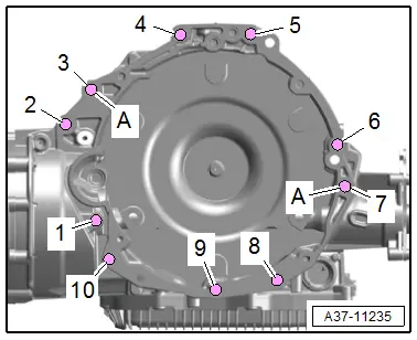
- Remove the starter bolts -1 and 2-.
- Press the starter off the transmission and leave it in the installation position.
- Remove the remaining bolts -3 through 10- that attach the engine to the transmission.
![]() Note
Note
Ignore -A-.
- Loosen the clamping screws on the sides of the Scissor Lift Table -VAS6131B- and pull the rear table top with the transmission toward the rear in direction of -arrow-.