Audi Q7: Engine, Removing
Special tools and workshop equipment required
- Engine Bung Set -VAS6122-
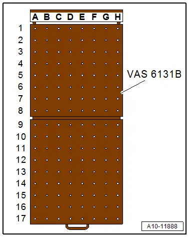
- Scissor Lift Table -VAS6131B-
- Scissor Lift Table - Audi Set -VAS6131/10-
- Scissor Lift Table - A8 Set -VAS6131/11-
- Scissor Lift Table - Q7 Set -VAS6131/13-
- Coolant Collection System -VAS5014- or Shop Crane - Drip Tray -VAS6208 -
- Hose Clip Pliers -VAS6340-
- Hose Clip Pliers -VAS6362-
- Used Oil Collection and Extraction Unit -SMN372500-
- Commercially available Step Ladder
 Caution
This procedure contains mandatory replaceable parts. Refer to component overview prior to starting procedure.
Mandatory Replacement Parts
- Bolts - Torque converter
- Bolt - Wheel bearing housing
- Bolts - Shock absorber fork
- Nuts - Shock absorber fork
- Nuts - Front Muffler
Procedure
 Note
Note
- With the lock carrier installed, the engine is removed downward together with the transmission and the subframe.
- During installation, all cable ties must be installed at the same location.
- All bolts on suspension components with bonded rubber bushings must be tightened in curb weight position (no load).
- Bonded rubber bushings have a limited range of rotation. Axle components with bonded rubber bushings must be brought into the position they will be in when driving before they are tightened (curb weight position). Otherwise, the bonded rubber bushing will have tension, which will reduce the service life.
- Before beginning work determine the curb weight position or prescribed level. Refer to → Suspension, Wheels, Steering; Rep. Gr.00; Repair Information.
 Note
Note
The electro-mechanical parking brake must be released before disconnecting battery so the driveshaft can be rotated to remove it.
- Position the front wheels so they are straight.
 Caution
Risk of destroying the electronic components.
Follow the steps for disconnecting the battery.
- Switch off the ignition.
- Disconnect the ground cable from the battery terminal. Refer to → Electrical Equipment; Rep. Gr.27; Battery; Battery, Disconnecting and Connecting.
 WARNING
Risk of scalding due to hot steam and hot coolant.
- The cooling system is under pressure when the engine is warm.
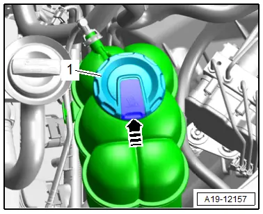
- Cover the coolant expansion tank cap with a cloth and carefully open it to reduce the pressure.
- Open the cover -1- for the coolant expansion tank by pressing the retainer in direction of -arrow-.
- Remove the front wheels. Refer to → Suspension, Wheels, Steering; Rep. Gr.44; Wheels and Tires.
- Remove the left and right wheel housing liner front sections. Refer to → Body Exterior; Rep. Gr.66; Wheel Housing Liner; Front Wheel Housing Liner, Removing and Installing.
- Remove the noise insulations. Refer to → Body Exterior; Rep. Gr.66; Noise Insulation; Noise Insulation, Removing and Installing.
- Remove the left and right lower longitudinal members. Refer to → Body Exterior; Rep. Gr.50; Lock Carrier; Overview - Lock Carrier.
- Remove the driveshaft. Refer to → Rear Final Drive; Rep. Gr.39; Driveshaft; Driveshaft, Removing and Installing.
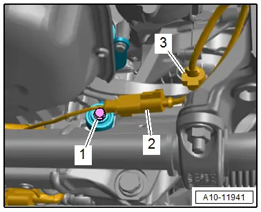
- Place the container of the Coolant Collection System -VAS5014- or the Shop Crane - Drip Tray -VAS6208- underneath.
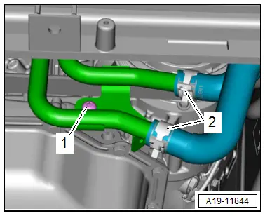
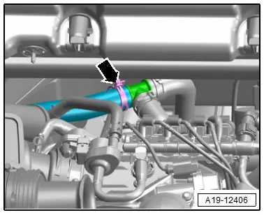
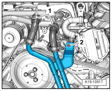
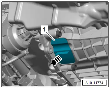
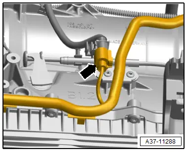
- Loosen the clamps -2- and drain any remaining coolant to remove the coolant hoses from the left front coolant pipes.
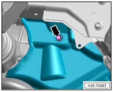
- Remove the bolt -1-.
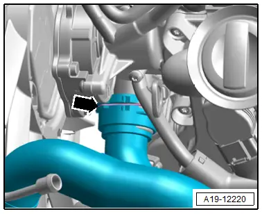
- Lift the clamp -1-, remove the coolant hose from the radiator and allow the coolant to drain.
- Equipped on some models: loosen the hose clamp -2- and remove the coolant hose from the radiator.
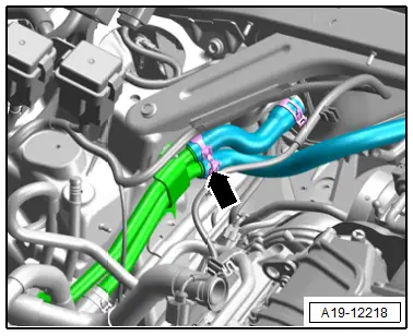
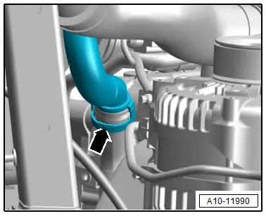
- Remove the coolant hose from the right coolant pipe on the transmission by loosening the hose clamp -arrow- and letting the coolant drain out.
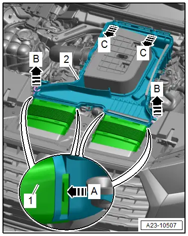
- Open the left and right clip in direction of -arrow B-.
- Remove the air filter upper section -1- in the center toward the rear from the ball pins in direction of -arrow A- and disengage from the air filter lower section.
- Remove the air filter upper section.
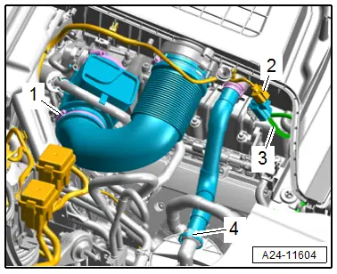
- Loosen the hose clamp -1- and remove the air duct pipe.
- Remove the secondary air injection hose -4- by pressing the catches on both sides.
- Disconnect the connector -2- for the Air Filter Bypass Door Valve -N275-.
- Remove the vacuum hose -3-.
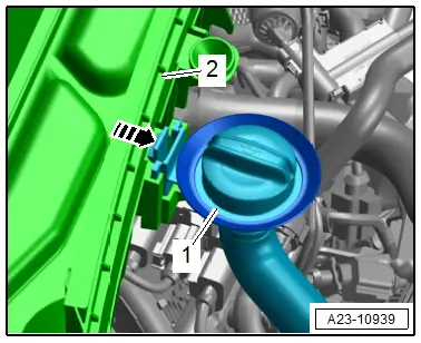
- Release the retainer in direction of -arrow- and oil filler tube -1- upward from the air filter lower section -2-.
- Release the retainer in direction of -arrow A- and remove the air ducts -1- from the air filter lower section -2-.
- Remove the front air filter lower section from the ball pin upward in direction of -B arrows- and then remove the rear mount toward the front in direction of -C arrows-.
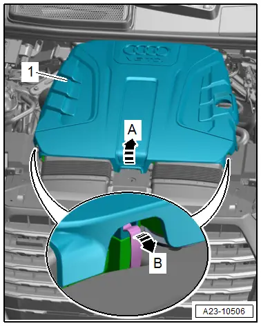
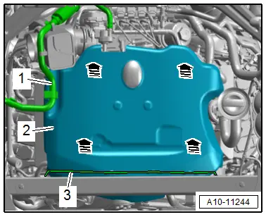
- Free up the vacuum hoses -1 and 3-.
- Carefully pull the engine cover -2- off of the retaining pins one after the other -arrows-. Do not pull sharply on the engine cover or pull it to one side.
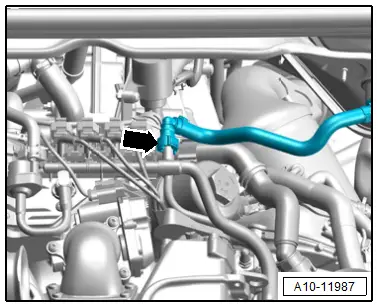
- Disconnect the vacuum connection -arrow- by pressing the release buttons on both sides.
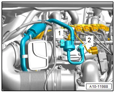
- Disconnect the connector -1- from the EVAP Canister Purge Regulator Valve 1 -N80-.
- Remove the vacuum hose -2- by pressing the release buttons on both sides.
- Disengage the EVAP Canister Purge Regulator Valve 1 -N80- from the bracket free it up and move to the side with the hoses connected.
 Caution
There is a risk of contamination.
Follow the guidelines for clean working conditions when working on the fuel supply system. Refer to → Chapter "Guidelines for Clean Working Conditions".
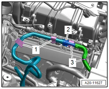
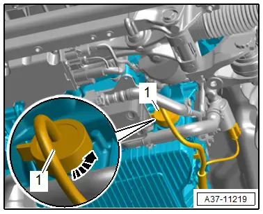
- Free up the fuel hose from the clips -1- and move it to the right side.
 WARNING
The fuel system is under pressure.
Risk of injury from fuel spraying out.
- Wear protective eyewear.
- Wear safety gloves.
- Reduce the pressure: place clean cloths around the connection point and carefully open the connection point.
- Disconnect the fuel hose -2-. Refer to → Fuel Supply - Gasoline Engines; Rep. Gr.20; Connector Couplings; Connector Couplings, Disconnecting.
- Always seal the open lines and connections with clean plugs from the Engine Bung Set -VAS6122-.
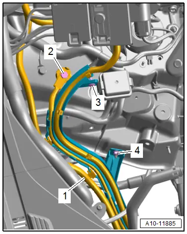
 Note
Note
Ignore -3-.
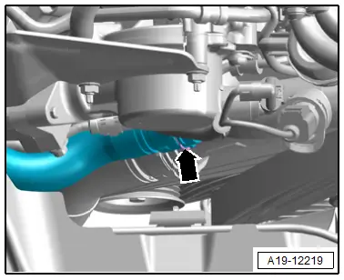
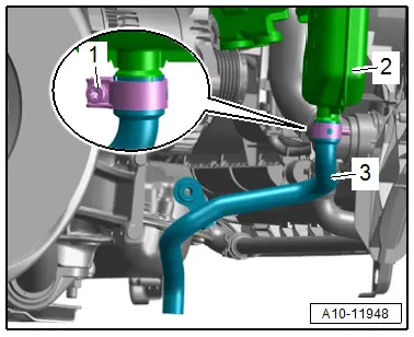
- Versions without parking/auxiliary heater: loosen the hose clamp -arrow- and remove the coolant hose.
- Versions with parking/auxiliary heater: loosen the hose clamp -arrow- and remove the coolant hose.
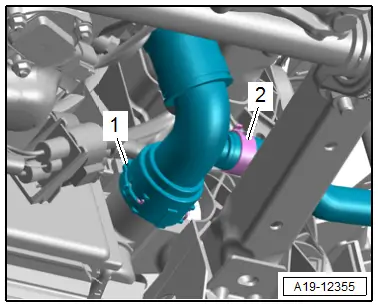
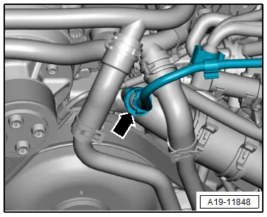
- Open the clamp and remove the right front coolant hose -arrow- from the front coolant pipe.
- Open the clamp -arrow- and remove the coolant line.
- Free up the coolant line and push it to the left side.
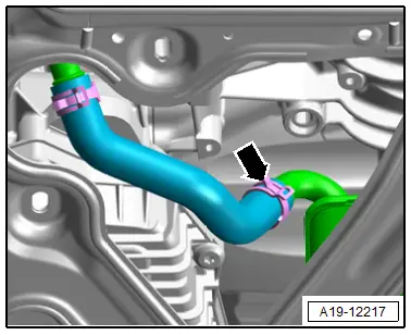
- Remove the coolant hose -arrow- from the front coolant pipe by lifting the clip.
- Remove the bolt -2- on the left front coolant pipes.
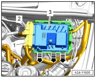
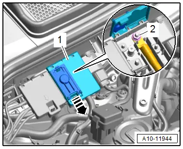
 Note
Note
- The installed position is shown in the illustration with the engine removed.
- Ignore -1-.
- Disconnect the connector -2-.
- Release the catches in direction of -arrows- remove the Engine Control Module -J623--3- and set it to the side.
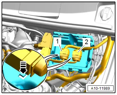
 Note
Note
Ignore -1-.
- Disconnect the connectors -1 and 2-.
- Release the catches in direction of -arrow- to remove the connectors to the side.
- Free up the engine wiring harness and set it on the engine.
- Release the latch in direction of -arrow- and open the E-box -1-.
- Remove the nut -2- and free up the B+ wire.
- Free up the wire -1- on the wiring duct.
- Remove the bolt -2- and free up the ground wire.
- Remove the bolt -3- and nut -4- and free up the wiring duct.
- Disconnect the left and right connector -3- for the electrohydraulic engine mount solenoid valve, and free up the wires.
- Remove the left connector -2- from the bracket, disconnect it and free up the wire.
 Note
Note
Ignore -1-.
 Caution
Risk of destroying by reversing the running direction on a used ribbed belt.
Before removing the ribbed belt, mark the running direction with chalk or a felt-tip pen for reinstallation.
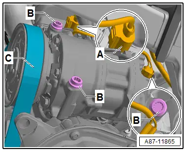
- To release the tension on the ribbed belt, pivot the tensioner clockwise in direction of -arrow- and then lock using a Locking Pin -T10060A-.
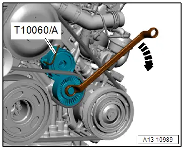
- Remove the ribbed belt -C- from the belt pulley of the air conditioning compressor.
- Disconnect the connector -A-.
 Caution
Risk of damaging the refrigerant lines and hoses.
Do not bend, twist or stretch the refrigerant lines and hoses.
- Remove the bolts -B-. Then remove the A/C compressor from the bracket and tie it up on the left side.
- Remove the bolts -arrows-. Then remove the A/C compressor from the bracket and tie it up on the left side.
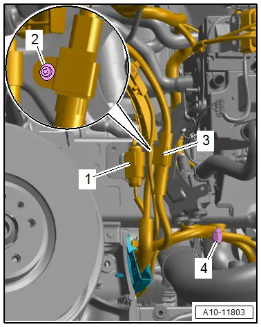
- Disconnect the secondary air hose -arrow- by pressing the release buttons on both sides.
- Remove the nut -4- and free up the ground wire.
- Remove the bolt -2-.
- Disconnect the connectors -1 and 3- and free up the wires.
 Note
Note
The version with the parking/auxiliary heater is shown.
- Versions with parking/auxiliary heater: loosen the screw-type clamp -1- and remove the exhaust pipe -3- from the muffler -2- for the parking/auxiliary heater.
- Disconnect the left and right connector -2- for the Right Front ABS Wheel Speed Sensor -G45-/Left Front ABS Wheel Speed Sensor -G47- and free up the wire.
 Note
Note
Ignore -1-.
- Equipped on some models: disconnect the connector -arrow- on the left and right sides for the Left Front Level Control System Sensor -G78-/Right Front Level Control System Sensor -G289- and free up the wire.
- Remove the brake caliper and secure it with the brake hose still attached inside the wheel housing with wire. Refer to → Brake System; Rep. Gr.46; Front Brakes; Brake Caliper, Removing and Installing.
 Caution
Risk of damaging the brake pistons.
Do not operate brake pedal when the brake caliper is removed.
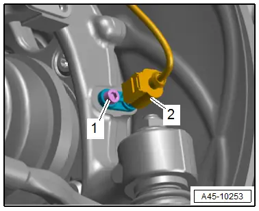
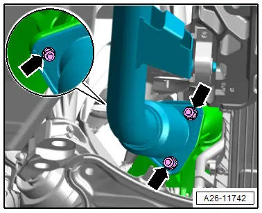
- Loosen the threaded connection -1-.
 Caution
There is a risk of damaging the wheel bearing housing.
The slits in the wheel bearing housing must not be widened using a chisel or similar tool!
- Remove the joint pins in the upper control arm -2- from the wheel bearing housing.
 Note
Note
Ignore -3 and 4-.
- Repeat the procedure on the other side of the vehicle.
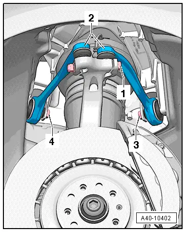
- Remove the left and right nut -4-.
 Note
Note
- The bolt -3- will be removed later.
- Ignore -1 and 2-.
- Remove the stabilizer bar. Refer to → Suspension, Wheels, Steering; Rep. Gr.40; Subframe; Stabilizer Bar, Removing and Installing.
- Remove the subframe crossbrace. Refer to → Suspension, Wheels, Steering; Rep. Gr.40; Subframe; Subframe Crossbrace, Removing and Installing.
 Caution
There is a risk of damaging the suspension components.
If the subframe mount, steering gear or subframe crossbrace are not installed correctly, do not rest the vehicle on its wheels.
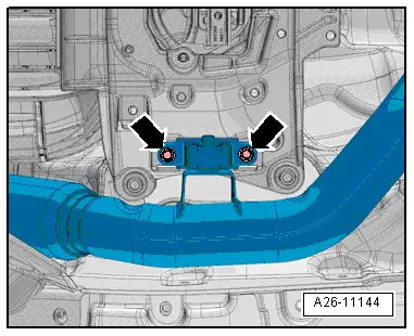
- Remove the left and right bolts -arrow- for the subframe shield.
- Remove the steering intermediate shaft from the steering gear and the push the splines together. Refer to → Suspension, Wheels, Steering; Rep. Gr.48; Steering Column; Steering Intermediate Shaft, Removing and Installing.
 Caution
Risk of damaging the decoupling element inside the front exhaust pipe.
Do not bend decoupling element in the front muffler more than 10º.
- Remove the left and right nuts -arrows- and the front muffler.
If the Engine Should Be Separated from the Transmission:
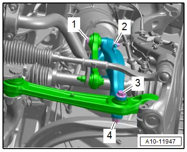
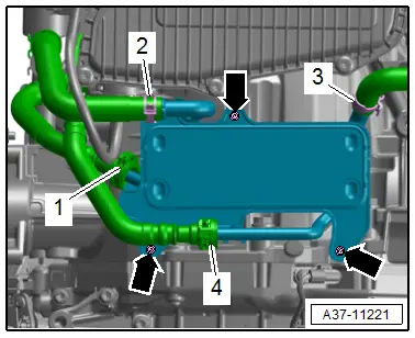
- Remove the bolts -arrows- and push the ATF cooler with the hoses -1, 2 and 4- attached.
 Note
Note
Ignore -3-.
- Remove the lower cover -1- from the transmission in direction of -arrow-.
- Counterhold the crankshaft and loosen the torque converter bolts using Crankshaft Socket -T40058- and a wrench.
 Note
Note
Only turn crankshaft only in direction of engine rotation in direction of -arrow-.
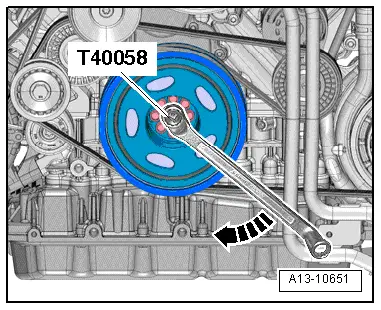
- Remove the six bolts -arrow- for the torque converter on the drive plate -1-. Turn the crankshaft an additional 60º in the direction of engine rotation.
Continuation of Engine Removal:
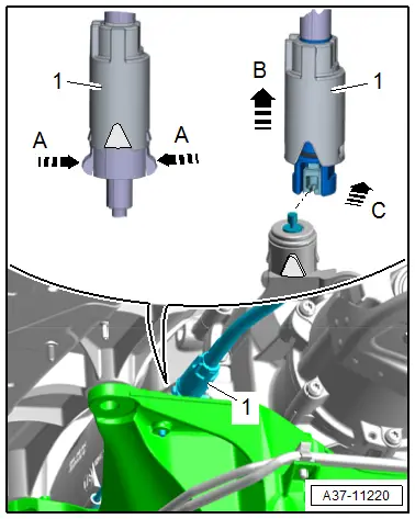
- Release the retainers in direction of -A arrows- and slide the sleeve -1- on the emergency release cable in the direction of -arrow B-.
- Disengage the rear section of the emergency release cable from the front section of the emergency release cable in direction of -arrow C-.
- Disconnect the connector -arrow- by opening the heat shield boot.
 Caution
Risk of destroying the transmission control module (Mechatronic) with static discharge.
- Before handling the connector, always "discharge" the static electricity. Do this by briefly touching a grounded object, for example the vehicle ground, the vehicle or the hoist.
- Do not touch connector terminals in the transmission connector with hands.
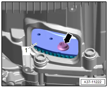
- Turn the twist lock counter-clockwise -arrow- and disconnect the connector -1- from the transmission.
- Free up the wiring harness on the transmission.
Scissor Lift Table, Preparing:
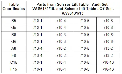
- Equip the Scissor Lift Table -VAS6131B- with Scissor Lift Table - Audi Set -VAS6131/10- and Scissor Lift Table - Q7 Set -VAS6131/13- as follows:
- Secure the mounting elements by hand on the Scissor Lift Table -VAS6131B-.
- Position the Scissor Lift Table -VAS6131B- so it is level.
- Note the bubble level (sight glass) on support platform.
- Guide the Scissor Lift Table -VAS6131B- under the engine/transmission subassembly.
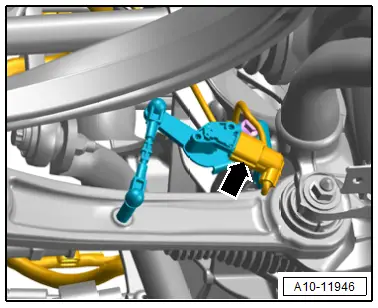
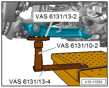
- Attach mounting elements from the Scissor Lift Table - Audi Set -VAS6131/10- and Scissor Lift Table - Q7 Set -VAS6131/13- at the left and right of the control arm, as shown.
- Make sure the threaded spindles are completely screwed in.
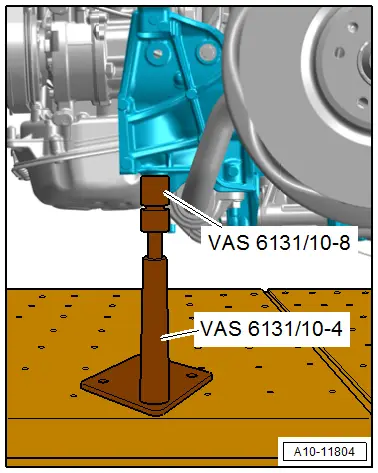
- Attach the mounting elements from the Scissor Lift Table - Audi Set -VAS6131/10- to the mounting element on the left and right front as shown.
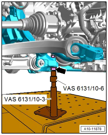
- Install the internal multi-point bolt -arrow- for the subframe crossbrace all the way into the subframe on the left and right sides.
- Attach the mounting elements from the Scissor Lift Table - Audi Set -VAS6131/10- to the multi-point bolts for the subframe crossbrace on the left and right sides as shown.
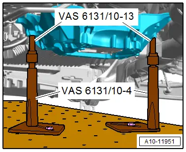
- Attach the mounting elements from the Scissor Lift Table - Audi Set -VAS6131/10- to the tunnel crossmember on the left and right sides as shown.
- Rotate all of the mounting element spindles upward until all the mounting pins come in contact with the mounting points.
- Tighten the mounting element base plates to 20 Nm on the Scissor Lift Table -VAS6131B-.
- Secure the subframe. Refer to → Suspension, Wheels, Steering; Rep. Gr.40; Subframe; Subframe, Lowering.
- Remove the bolts -arrows- on the tunnel crossmember.
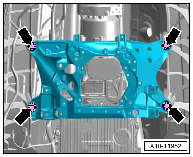
- Remove the left and right bolts -3-.
 Note
Note
The threaded connections -1, 2 and 4- are already separated.
 Caution
Risk of damaging the hose and line connections as well as the engine compartment.
- Make sure all the hose and line connections between the engine, transmission, subframe and body have been disconnected.
- Carefully guide the engine/transmission assembly with the subframe out of engine compartment when lowering.
- Carefully guide the suspension struts on the longitudinal members.
- Lower the Scissor Lift Table -VAS6131B- with the engine/transmission assembly and remove from under the vehicle.


