Audi Q7: Filter, Removing and Installing
Special tools and workshop equipment required
- Torque Wrench 1783 - 2-10Nm -VAG1783-
Removing
 Note
Note
Follow the guidelines for clean working conditions. Refer to → Chapter "Guidelines for Clean Working Conditions".
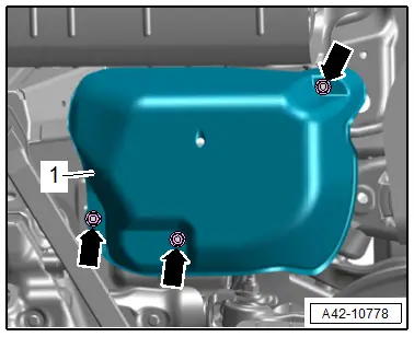
- Remove the nuts -arrows-, and remove the cover -1- for the air supply unit.

- Loosen the clamps -arrows-, remove the intake hoses and immediately protect them from dirt.
- Unclip the air filter -1- from the bracket and remove.
Installing
Install in reverse order of removal.
Tightening Specifications
- Refer to → Chapter "Overview - Air Supply Unit"
Solenoid Valve Block, Removing and Installing
Special tools and workshop equipment required
- Torque Wrench 1410 -VAG1410-
- Torque Wrench 1783 - 2-10Nm -VAG1783-
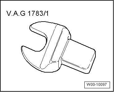
- Torque Wrench 1783 - Open Jaw - 10mm -VAG1783/1-
Removing
 Note
Note
Follow the guidelines for clean working conditions. Refer to → Chapter "Guidelines for Clean Working Conditions".
- Vent the system. Refer to → Chapter "Air Suspension System, Filling and Bleeding".
- Switch off the ignition.
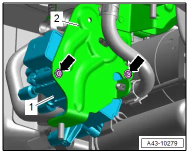
- Remove the nuts -arrows-, and remove the cover -1- for the air supply unit.
- Disconnect the connector -3- from the solenoid valve -1-.
- Remove the air lines -2- and -arrows- and protect them from dirt.
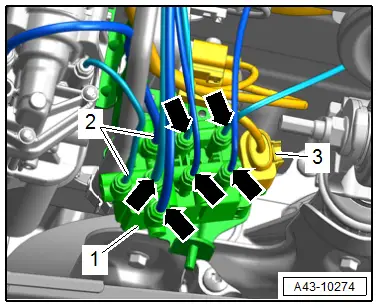
- Remove the bolts -arrows- and the solenoid valve -1- from the bracket -2-.
Installing
Install in reverse order of removal and note the following:
- Fill the system. Refer to → Chapter "Air Suspension System, Filling and Bleeding".
Tightening Specifications
- Refer to → Chapter "Overview - Air Supply Unit"
Pressure Reservoir, Removing and Installing
Special tools and workshop equipment required
- Torque Wrench 1783 - 2-10Nm -VAG1783-
 Note
Note
The procedure for the left side of the vehicle is described.
Removing
 Note
Note
Follow the guidelines for clean working conditions. Refer to → Chapter "Guidelines for Clean Working Conditions".
- Vent the system. Refer to → Chapter "Air Suspension System, Filling and Bleeding".
- Switch off the ignition.
- Remove the air duct to the vent from the B-pillar. Refer to → Body Interior; Rep. Gr.70; Vehicle Interior Trim Panels; Overview - B-Pillar Trim Panel.
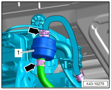
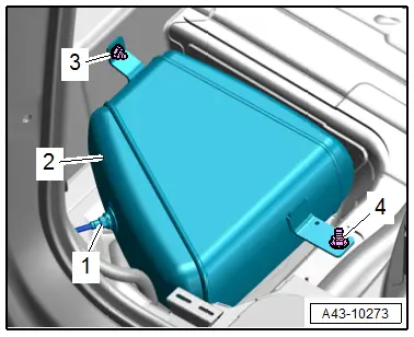
- Slowly loosen air line -1- on pressure reservoir -2- and allow air pressure to come down. After the air pressure has escaped, remove the air line.
- Remove the bolts -3- and nut -4- and remove the pressure reservoir.
Installing
Install in reverse order of removal and note the following:
- Fill the system. Refer to → Chapter "Air Suspension System, Filling and Bleeding".
Tightening Specifications
- Refer to → Fig. "Pressure Reservoir - Tightening Specification"
Special Tools
Special tools and workshop equipment required
- Torque Wrench 1410 -VAG1410-
- Torque Wrench 1783 - 2-10Nm -VAG1783-
- Torque Wrench 1783 - Open Jaw - 10mm -VAG1783/1-
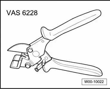
- Hose Cutting Pliers -VAS6228-
- If the Bonding Agent -D 355 205 A2- dries longer than 3 hours, then it must be primed again.