Audi Q7: Front Passenger Airbag
Overview - Front Passenger Airbag
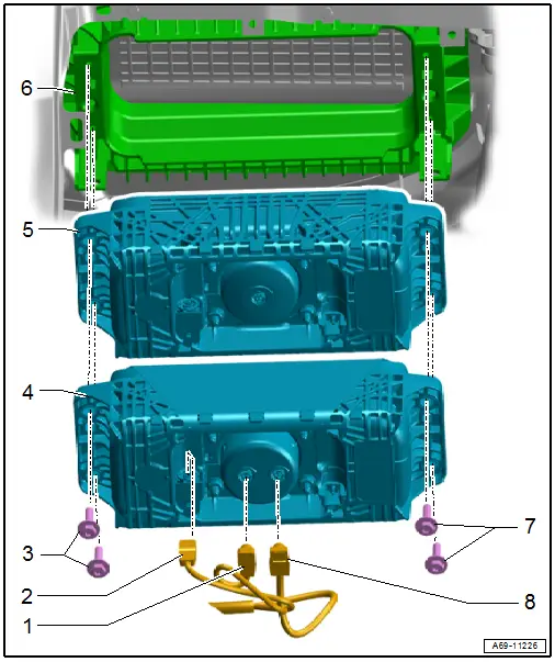
1 - Connector
- For Front Passenger Airbag Igniter 2 -N132-
2 - Connector
- For Front Passenger Airbag Release Valve Igniter -N491-
3 - Bolts
- 9 Nm
- Replace after removing
4 - Dual-Stage Front Passenger Airbag
- With
- Front Passenger Airbag Igniter 1 -N131-
- Front Passenger Airbag Igniter 2 -N132-
- Front Passenger Airbag Release Valve Igniter -N491-
 WARNING
Risk of injury due to pyrotechnic components.
Pay attention to the safety precautions when working with pyrotechnic components. Refer to → Chapter "Safety Precautions for Pyrotechnic Components".
- Removing and installing. Refer to → Chapter "Front Passenger Airbag Unit with Igniter, Removing and Installing".
5 - Single-Stage Front Passenger Airbag
- With
- Front Passenger Airbag Igniter 1 -N131-
- Front Passenger Airbag Release Valve Igniter -N491-
 WARNING
Risk of injury due to pyrotechnic components.
Pay attention to the safety precautions when working with pyrotechnic components. Refer to → Chapter "Safety Precautions for Pyrotechnic Components".
- Removing and installing. Refer to → Chapter "Front Passenger Airbag Unit with Igniter, Removing and Installing".
6 - Instrument Panel
- Replace the instrument panel after an airbag has deployed. Refer to → Chapter "Instrument Panel, Removing and Installing".
7 - Bolts
- 9 Nm
- Replace after removing
8 - Connector
- For Front Passenger Airbag Igniter 1 -N131-
Front Passenger Airbag Unit with Igniter, Removing and Installing
Mandatory Replacement Parts
- Bolts - Front Passenger Airbag Unit with Igniter
Removing
 WARNING
- Follow all safety precautions when working on pyrotechnic components. Refer to → Chapter "Safety Precautions for Pyrotechnic Components".
- Follow all regulations when disposing of pyrotechnic components. Refer to → Chapter "Airbag, Belt Tensioner and Battery Cut-Out Units, Storing, Transporting and Disposing (Pyrotechnic Components)".
- Follow the allocation of the airbag unit to the instrument panel. Refer to the Parts Catalog.
- Disconnect the battery ground cable with the ignition turned on. Refer to → Electrical Equipment; Rep. Gr.27; Battery; Battery, Disconnecting and Connecting.
- Remove the glove compartment. Refer to → Chapter "Glove Compartment, Removing and Installing".
- Remove front passenger side instrument panel vent. Refer to → Chapter "Passenger Side Instrument Panel Vent, Removing and Installing".
- Remove the air duct to the right instrument panel vent and to the wide vent. Refer to → Heating, Ventilation and Air Conditioning; Rep. Gr.87; Air Duct; Overview - Air Routing and Air Distribution in Vehicle Interior.
 WARNING
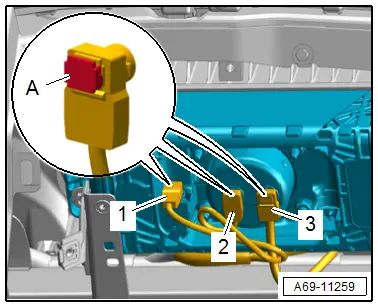
Before handling pyrotechnic components (for example, disconnecting the connector), the person handling it must "discharge static electricity". This can be done by briefly touching the door striker pin, for example.
- Release the connector lock -A- with a small screwdriver.
- Disconnect the connectors -1, 2 and 3- on the Front Passenger Airbag Igniter 1 - N131-, Front Passenger Airbag Igniter 2 - N132- and Front Passenger Airbag Release Valve Igniter - N491-.
 Note
Note
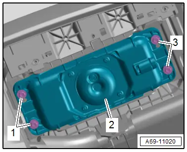
Secure the airbag from falling.
- Remove the bolts -1 and 3-.
- Remove the passenger airbag -2- downward.
 WARNING
Set the airbag down so the impact cushion faces upward.
Installing
 WARNING
- Follow all safety precautions when working on pyrotechnic components. Refer to → Chapter "Safety Precautions for Pyrotechnic Components".
- Before handling pyrotechnic components (for example, connecting the connector), the person handling it must "discharge static electricity". This can be done by briefly touching the door striker pin, for example.
- Follow the allocation of the airbag to the instrument panel. Refer to the Parts Catalog.
Install in reverse order of removal and note the following:
- Connect the connector -1- to the airbag igniter in direction of -arrow A-.
- Press in the connector lock -2- in direction of -arrow B-. While doing this, the connector is pushed into the airbag igniter and locks into place.
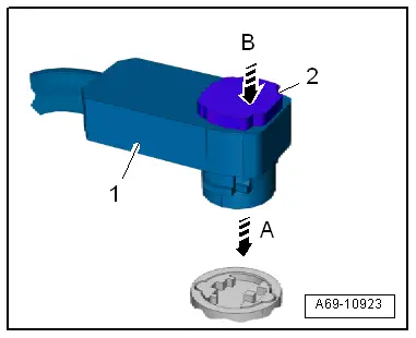
 Note
Note- Make sure the connectors are pushed in all the way and that they engage audibly.
- Make sure the wires are not pinched.
 WARNING
Repairing pyrotechnic components (for example the airbag and seat belt tensioner) incorrectly increases the risk of unintentional deployments when the battery is connected.
- The ignition must be on when connecting the battery.
- For personal safety when connecting the battery, stay out of the deployment area of the airbag and maintain a distance from the seat belt tensioners/seat belts.
- Make sure that there are no other people inside the vehicle at the time when the battery is connected.
- Connect the battery ground cable with the ignition turned on. Refer to → Electrical Equipment; Rep. Gr.27; Battery; Battery, Disconnecting and Connecting.
 Note
Note
If the Airbag Indicator Lamp -K75- signals a fault after installing, check the Diagnostic Trouble Code (DTC) memory, erase it and check it again use the Vehicle Diagnostic Tester.
Information for installation: for example, tightening specifications, replacing body parts. Refer to → Chapter "Overview - Front Passenger Airbag" and → Chapter "Overview - Instrument Panel".

