Audi Q7: Instrument Cluster with Instrument Cluster Control Module -J285-, Removing and Installing
Instrument Cluster with Instrument Cluster Control Module -J285-, Removing and Installing, Low Instrument Cluster
Special tools and workshop equipment required
- Fiber-Optic Repair Set - Connector Protective Caps -VAS6223/9- from Fiber-Optic Repair Set -VAS6223B-
- If the control module (instrument cluster) is replaced, select the "Replace control module" function for the corresponding control module using the Vehicle Diagnostic Tester.
Removing
- Move the steering wheel as far to the rear and down as possible. Use the full steering column adjustment range for this.
- Switch off the ignition and place the ignition key outside of the vehicle.
- Remove the instrument cluster trim. Refer to → Body Interior; Rep. Gr.70; Instrument Panel; Instrument Cluster Trim, Removing and Installing.
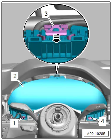
- Remove the bolts -1 and 4-.
- Release the retainers -3--arrow-.
- Pivot the instrument cluster -2- to the rear.
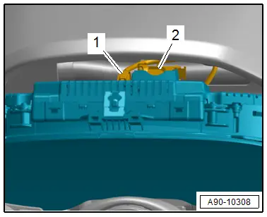
- Disconnect the connectors:
1 - For the fiber-optic cable
2 - For the instrument cluster
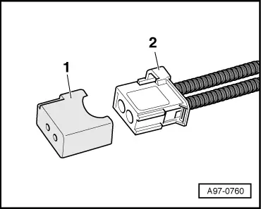
- Seal the open wiring harness connector -2- of the fiber-optic cable with the Fiber-Optic Repair Set - Connector Protective Caps -VAS6223/9--1-.
TIP
The protective cap prevents contamination of or mechanical damage to the front surface of the fiber-optic cable which would impair light transmission.
- Remove the instrument cluster on the front passenger side between the steering wheel and the instrument panel.
Installing
Install in reverse order of removal and note the following:
- Follow the instructions on the Vehicle Diagnostic Tester display with a new instrument cluster.
Tightening Specifications
- Refer to → Chapter "Overview - Instrument Cluster"
Instrument Cluster with Instrument Cluster Control Module -J285-, Removing and Installing, Instrument Cluster High
Special tools and workshop equipment required
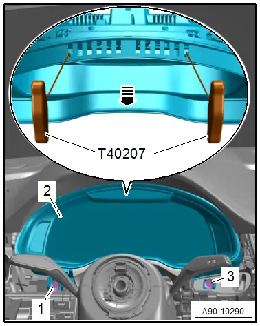
- Quantity: 2 Hook Tool -T40207- (High - Instrument Cluster Version)
- Fiber-Optic Repair Set - Connector Protective Caps -VAS6223/9- from Fiber-Optic Repair Set -VAS6223B-
- If the control module (instrument cluster) is replaced, select the "Replace control module" function for the corresponding control module using the Vehicle Diagnostic Tester.
Removing
- Remove the driver side vents in the instrument panel. Refer to → Body Interior; Rep. Gr.70; Instrument Panel; Instrument Panel Vent, Removing and Installing.
- Remove the access/start authorization switch trim. Refer to → Body Interior; Rep. Gr.70; Instrument Panel; Access/Start Authorization Switch Trim, Removing and Installing.
- Remove the bolts -1 and 3-.
- Guide both -T40207- between the instrument panel and instrument cluster and attach at the outer vent openings as shown.
- Using both -T40207-, carefully remove the instrument cluster -2- from the retainer in direction of -arrow- and tilt toward the rear.
- Disconnect the connectors:
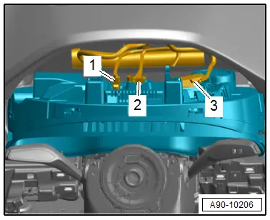
1 - For the fiber-optic cable
2 - For the antenna
3 - For the instrument cluster
- Seal the open wiring harness connector -2- of the fiber-optic cable with the Fiber-Optic Repair Set - Connector Protective Caps -VAS6223/9--1-.

TIP
The protective cap prevents contamination of or mechanical damage to the front surface of the fiber-optic cable which would impair light transmission.
- Remove the instrument cluster on the front passenger side between the steering wheel and the instrument panel.
Installing
Install in reverse order of removal and note the following:
- Follow the instructions on the Vehicle Diagnostic Tester display with a new instrument cluster.
Tightening Specifications
- Refer to → Chapter "Overview - Instrument Cluster"

