Audi Q7: Left/Right Rear Upper Body Vent Temperature Sensor -G635-/-G636-, Removing and Installing
Left Rear Upper Body Vent Temperature Sensor -G635-, Removing and Installing
 Note
Note
The Left Rear Upper Body Vent Temperature Sensor -G635- is only installed on vehicles with a "High" A/C system (a rear heater and A/C unit). On a vehicle with a "Mid" or "Mix" A/C system the installation opening in the air duct is sealed.
Removing
- Move the left front seat (driver seat) all the way to the front.
- Turn off the ignition.
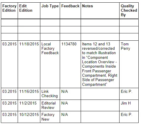
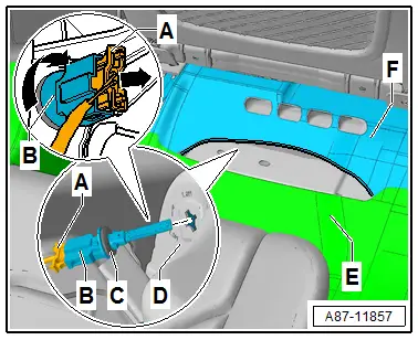
- Carefully detach the outer left rear floor covering -E- from the vehicle so that the Left Rear Upper Body Vent Temperature Sensor -G635--B- (installed in the air duct to the left rear upper body vent -D-) is accessible.
- Disengage and disconnect the connector -A-.
- Turn the sensor -B- 90º and remove it from the air duct -D-.
Installing
Install in reverse order of removal. Note the following:
- Check the seal -C- for damage and proper seating.
- Check the event memory of the front A/C display control head, the Front A/C Display Control Head -E87- (and the Rear A/C Display Control Head -E265-) and erase any displayed malfunctions. Refer to Vehicle Diagnostic Tester in the "Guided Fault Finding" function if necessary.
Right Rear Upper Body Vent Temperature Sensor -G636-, Removing and Installing
 Note
Note
The Left Rear Upper Body Vent Temperature Sensor -G635- is only installed on vehicles with a "High" A/C system (a rear heater and A/C unit). On a vehicle with a "Mid" or "Mix" A/C system the installation opening in the air duct is sealed.
Removing
- Move the right front seat (passenger side seat) as far forward as possible.
- Turn off the ignition.
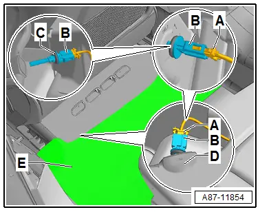
- Carefully detach the outer right rear floor covering -E- from the vehicle so that the Right Rear Upper Body Vent Temperature Sensor -G636--B- (installed in the air duct to the right rear upper body vent -D-) is accessible.
- Disengage and disconnect the connector -A-.
- Turn the sensor -B- 90º and remove it from the air duct -D-.
Installing
Install in reverse order of removal. Note the following.
- Check the seal -C- for damage and proper seating.
- Check the event memory of the front A/C display control head, the Front A/C Display Control Head -E87- (and the Rear A/C Display Control Head -E265-) and erase any displayed malfunctions. Refer to Vehicle Diagnostic Tester in the "Guided Fault Finding" function if necessary.
Left/Right Rear Footwell Vent Temperature Sensor -G637-/-G638- , Removing and Installing
Left Rear Footwell Vent Temperature Sensor -G637-, Removing and Installing
 Note
Note
The Left Rear Upper Body Vent Temperature Sensor -G635- is only installed on vehicles with a "High" A/C system (a rear heater and A/C unit). On a vehicle with a "Low", "Mid" or "Mix" A/C system the installation opening in the air duct is sealed.
Removing
- Move the left front seat (driver seat) all the way to the front.
- Turn off the ignition.
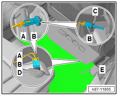
- Loosen the left rear carpet -E- carefully from the vehicle so that the front carpet -F- can be slightly lifted.
- Lift the left front carpet rear -F- in the center carefully until the Right Rear Upper Body Vent Temperature Sensor -G636--B- (installed in the air duct to the vent for the left rear footwell -D-) is accessible.
- Disengage and disconnect the connector -A-.
- Turn the sensor -B- about 90º and remove it from the air duct to the vent for the left rear footwell -D-.
Installing
Install in reverse order of removal. Note the following.
- Check the seal -C- for damage and proper seating.
- Ensure that the footwell vent trims under the front seat are in the correct installation position.
- Check the event memory of the front A/C display control head, the Front A/C Display Control Head -E87- (and the Rear A/C Display Control Head -E265-) and erase any displayed malfunctions. Refer to Vehicle Diagnostic Tester in the "Guided Fault Finding" function if necessary.
Right Rear Footwell Vent Temperature Sensor -G638-, Removing and Installing
 Note
Note
The Left Rear Upper Body Vent Temperature Sensor -G635- is only installed on vehicles with a "High" A/C system (a rear heater and A/C unit). On a vehicle with a "Low", "Mid" or "Mix" A/C system the installation opening in the air duct is sealed.
Removing
- Move the right front seat (passenger side seat) as far forward as possible.
- Turn off the ignition.
- Loosen the right rear carpet -E- carefully from the vehicle so that the front carpet -F- can be slightly lifted.
- Lift the right front carpet rear -F- in the center carefully until the Right Rear Footwell Vent Temperature Sensor -G638--B- (installed in the air duct to the vent for the right rear footwell -D-) is accessible.
- Disengage and disconnect the connector -A-.
- Turn the sensor -B- about 90º and remove it from the air duct to the vent for the right rear footwell -D-.
Installing
Install in reverse order of removal. Note the following.
- Check the seal -C- for damage and proper seating.
- Ensure that the footwell vent trims under the front seat are in the correct installation position.
- Check the event memory of the front A/C display control head, the Front A/C Display Control Head -E87- (and the Rear A/C Display Control Head -E265-) and erase any displayed malfunctions using the. Refer to Vehicle Diagnostic Tester in the "Guided Fault Finding" function if necessary.
Special Tools
Special tools and workshop equipment required
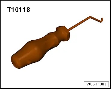
- Elbow Assembly Tool -T10118-
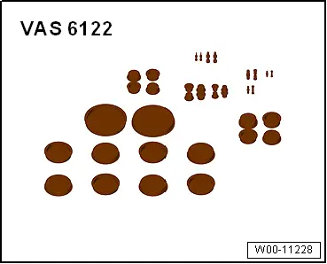
- Engine Bung Set -VAS6122-
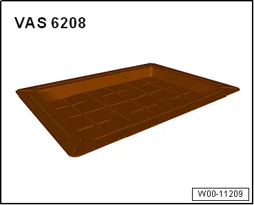
- Container of the Coolant Collection System -VAS5014- or the Shop Crane - Drip Tray -VAS6208-
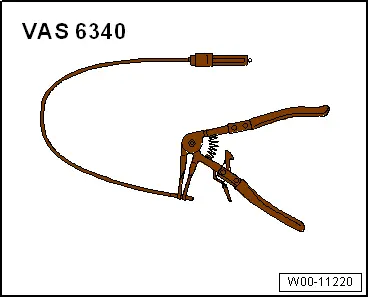
- Hose Clip Pliers -VAS6340-
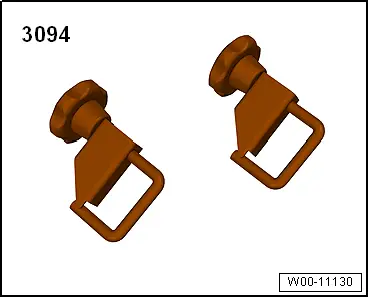
- Hose Clamps - Up To 25mm -3094-
- Not Illustrated:
- Hose Clamps - Up To 40mm -3093-
- Cooling System Tester -VAG1274B- (and corresponding adapters)
- Refrigerant Sockets -T10364-
- Cleaning Solution -D 009 401 04-
- Commercial compressed-air gun with rubber end piece
Revision History
DRUCK NUMBER: A005A009921