Audi Q7: Luggage Compartment Floor Trim Panel, Removing and Installing
Luggage Compartment Floor Trim Panel, Removing and Installing, Vehicles without High-Voltage System
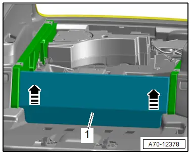
Removing
- Remove the luggage compartment floor.
- Fold the second row seats forward.
- Disengage the luggage compartment floor trim panel -1- at the side of the luggage compartment floor support -arrows- and remove.
Installing
Install in reverse order of removal.
Installation instructions: for example tightening specifications, replacing components. Refer to → Chapter "Overview - Luggage Compartment Floor, Vehicles without High-Voltage System".
Luggage Compartment Floor Trim Panel, Removing and Installing, Vehicles with High-Voltage System
Special tools and workshop equipment required
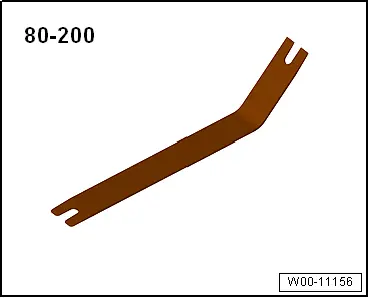
- Pry Lever -80-200-
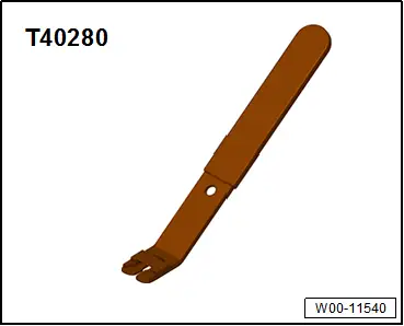
- Omega Clip Tool -T40280-
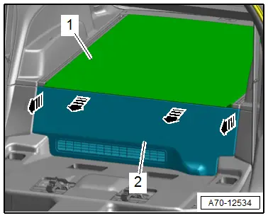
Removing
- Fold the second row seats forward.
- Fold up the front of the luggage compartment floor -1- over the luggage compartment floor trim panel.
- Unclip the luggage compartment floor trim panel -2- using the -80-200--arrows- and remove it.
Installing
Install in reverse order of removal.
Installation instructions: for example tightening specifications, replacing components. Refer to → Chapter "Overview - Luggage Compartment Floor, Vehicles with High-Voltage System".
Luggage Compartment Floor Trim Panel Bracket, Removing and Installing, Vehicles with High-Voltage System
Special tools and workshop equipment required
- Trim Removal Wedge -3409-
Removing
- Remove the luggage compartment floor panel. Refer to → Chapter "Luggage Compartment Floor, Removing and Installing, Vehicle with High-Voltage System".
- Remove the luggage compartment floor trim panel. Refer to → Chapter "Luggage Compartment Floor Trim Panel, Removing and Installing, Vehicles with High-Voltage System".
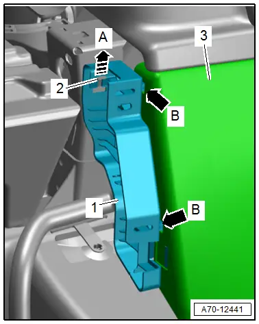
- Disengage the luggage compartment floor trim panel bracket -1- upward -arrow A- from the mount -2-.
- Disengage the tabs -B arrows- from the sill panel -3- using the -3409-.
- Disengage the luggage compartment floor trim panel bracket from the sill panel and remove it.
Installing
Install in reverse order of removal.
Installation instructions: for example tightening specifications, replacing components. Refer to → Chapter "Overview - Luggage Compartment Floor, Vehicles with High-Voltage System".
Luggage Compartment Support, Removing and Installing
Removing
- Front passenger side: if installed, remove the luggage compartment floor. Refer to → Chapter "Luggage Compartment Floor, Removing and Installing, Upright Spare Tire".
- Remove the luggage compartment floor trim panel. Refer to → Chapter "Luggage Compartment Floor Trim Panel, Removing and Installing, Vehicles without High-Voltage System".
- Remove the luggage compartment side trim panel. Refer to → Chapter "Luggage Compartment Side Trim Panel, Removing and Installing".
- Remove the tie down. Refer to → Chapter "Tie Down, Removing and Installing".
- Equipped on some models: remove the rail. Refer to → Chapter "Rail, Removing and Installing".
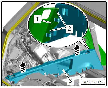
- Lift up the luggage compartment floor support -3-, disengage the tabs -2- on the support and remove the sill panel strip -1-.
- Disengage the luggage compartment floor support upward -arrows- and remove toward the rear.
Installing
- Mount the luggage compartment floor support with tie downs or rails and tighten the bolts only hand-tight.
- Install the luggage compartment floor.
- Tighten the tie downs or rails.
Further installation is the reverse order of removal.
Installation instructions: for example tightening specifications, replacing components. Refer to → Chapter "Overview - Luggage Compartment Floor".
Lock Carrier Trim Panel, Removing and Installing
Special tools and workshop equipment required
- Omega Clip Tool -T40280-
Removing
- Remove the luggage compartment floor.
- Vehicle with high-voltage system: remove the luggage compartment floor. Refer to → Chapter "Luggage Compartment Floor, Removing and Installing, Vehicle with High-Voltage System".
- Versions with upright spare tire: remove the luggage compartment floor. Refer to → Chapter "Luggage Compartment Floor, Removing and Installing, Upright Spare Tire".
- Equipped on some models: remove the emergency triangle.
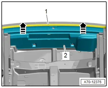
- Free up the lock carrier trim panel near the rear lid seal -1-.
 Caution
There is a risk of damage the wires.
Be careful when unclipping and do not lift the trim panel too high.
- Grip the trim panel -2- by hand and carefully pull vertically upward -arrows-.
- Disconnect the connector and remove the lock carrier trim panel.
Installing
Install in reverse order of removal.
Installation instructions: for example tightening specifications, replacing components. Refer to → Chapter "Overview - Luggage Compartment Side Trim Panel".

