Audi Q7: Overview - Instrument Cluster
Audi Q7 (4M) 2016-2026 Workshop Manual / Electrical System / Electrical Equipment / Instruments / Overview - Instrument Cluster
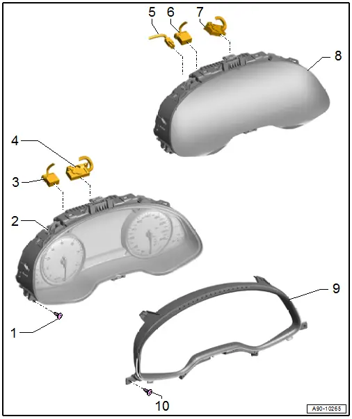
1 - Bolt
- 3 Nm
- Quantity: 2
2 - Instrument Cluster - Low
- With Instrument Cluster Control Module -J285-
- Do not disassemble
- If an LED for the indicator lamps or instrument cluster illumination is faulty, the instrument cluster must be replaced
- Removing and installing. Refer to → Chapter "Instrument Cluster with Instrument Cluster Control Module -J285-, Removing and Installing, Low Instrument Cluster".
3 - Fiber Optic Cable Connector
- Seal with Fiber-Optic Repair Set - Connector Protective Caps -VAS6223/9-
4 - Connector
- For the instrument cluster
5 - Antenna Wire
6 - Fiber Optic Cable Connector
- Seal with Fiber-Optic Repair Set - Connector Protective Caps -VAS6223/9-
7 - Connector
- For the instrument cluster
8 - Instrument Cluster - High
- With Instrument Cluster Control Module -J285-
- Do not disassemble
- The instrument cluster must be replaced if there is a malfunction.
- Removing and installing. Refer to → Chapter "Instrument Cluster with Instrument Cluster Control Module -J285-, Removing and Installing, Instrument Cluster High".
9 - Instrument Cluster Trim
- Removing and installing. Refer to → Body Interior; Rep. Gr.70; Instrument Panel; Instrument Cluster Trim, Removing and Installing.
10 - Bolt
- Quantity: 2
- Tightening specification. Refer to → Body Interior; Rep. Gr.70; Instrument Panel; Overview - Instrument Panel.
Overview - Windshield Projection (Head up Display)
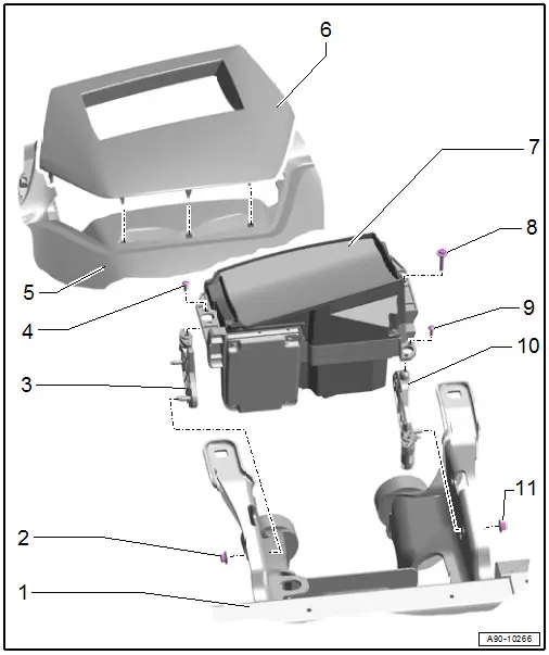
1 - Central Tube
2 - Nut
- 8 Nm
- Quantity: 3
3 - Exterior Bracket
- For windshield projection control module
- Removing and installing. Refer to → Chapter "Windshield Projection Head Up Display Control Module, Removing and Installing".
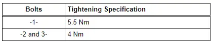
4 - Bolt
- Quantity: 2
- Tightening sequence. Refer to → Fig. "Windshield Projection Head Up Display Control Module - Tightening Specification and Sequence".
5 - Instrument Panel
6 - Upper Cover
- Removing and installing. Refer to → Body Interior; Rep. Gr.70; Instrument Panel; Overview - Instrument Panel
7 - Windshield Projection Head Up Display Control Module -J898-
- Removing and installing. Refer to → Chapter "Windshield Projection Head Up Display Control Module, Removing and Installing".
- Calibrating. Refer to → Chapter "Windshield Projection Head Up Display Control Module, Calibrating".
8 - Bolt
- Tightening sequence. Refer to → Fig. "Windshield Projection Head Up Display Control Module - Tightening Specification and Sequence".
9 - Bolt
- Quantity: 2
- Tightening sequence. Refer to → Fig. "Windshield Projection Head Up Display Control Module - Tightening Specification and Sequence".
10 - Interior Bracket
- For windshield projection control module
- Removing and installing. Refer to → Chapter "Windshield Projection Head Up Display Control Module, Removing and Installing".
11 - Nut
- 8 Nm
- Quantity: 3
Windshield Projection Head Up Display Control Module - Tightening Specification and Sequence
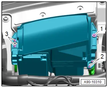
- Tighten the bolts in sequence shown.