Audi Q7: Overview - Subframe
Audi Q7 (4M) 2016-2026 Workshop Manual / Chassis / Suspension, Wheels, Steering / Rear Suspension / Overview - Subframe
 Caution
There is a risk of damaging the threads on the subframe threaded connection to the body.
- The subframe bolts on the body must not be loosened or tightened with an impact wrench.
- Always install all bolts by hand for the first few turns.
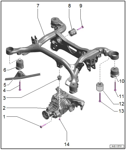
1 - Bolt
- Tightening specification. Refer to → Rep. Gr.10; Subframe Mount; Overview - Subframe Mount.
2 - Rear Final Drive
3 - Additional Bearing
- For the rear final drive
- Removing and installing. Refer to → Rep. Gr.10; Subframe Mount; Overview - Subframe Mount.
4 - Bolt
- 130 Nm +180º
- Replace after removing
5 - Diagonal Brace
- Overview. Refer to → Body Exterior; Rep. Gr.66; Underbody Trim Panel.
6 - Front Hydraulic Bonded Rubber Bushing
- For the subframe
- Removing and Installing. Refer to → Chapter "Subframe Front Hydraulic Bonded Rubber Bushing, Replacing".
- Installation position. Refer to → Fig. "Subframe Hydraulic Front Bonded Rubber Bushing Installation Position".
7 - Subframe
- Removing and installing. Refer to → Chapter "Subframe, Removing and Installing".
8 - Rear Bonded Rubber Bushing
- For the rear final drive
- Removing and installing. Refer to → Chapter "Rear Bonded Rubber Bushing for Rear Final Drive, Removing and Installing".
- Installation position. Refer to → Fig. "Rear Bonded Rubber Bushings Installation Position For The Rear Final Drive".
9 - Bolt
- Tightening specification. Refer to → Rep. Gr.10; Subframe Mount; Overview - Subframe Mount.
10 - Rear Bonded Rubber Bushing
- For the subframe
11 - Bolt
- 130 Nm +180º
- Replace after removing
12 - Vibration Damper
- Installation position. Refer to → Fig. "Vibration Damper Installation Position".
13 - Bolt
- 50 Nm +180º
- Replace after removing
14 - Nut
- Tightening specification. Refer to → Rep. Gr.10; Subframe Mount; Overview - Subframe Mount.
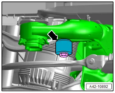
Vibration Damper Installation Position
- The beveled surface -arrow- must point upward.
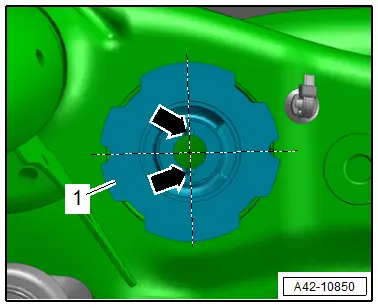
Subframe Hydraulic Front Bonded Rubber Bushing Installation Position
- The groves -arrows- are perpendicular to the direction of travel.
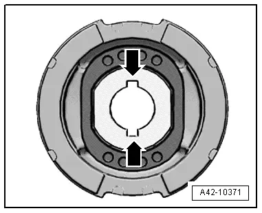
Rear Bonded Rubber Bushings Installation Position For The Rear Final Drive.
- The grooves -arrows- on the bonded rubber bushings -1- are at a right angle.