Audi Q7: Overview - Suspension Strut, Shock Absorber and Spring
Overview - Suspension Strut, Shock Absorber and Spring, Coil Spring
Coil Spring
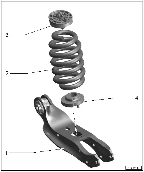
1 - Rear Lower Transverse Link
- Removing and installing. Refer to → Chapter "Rear Lower Transverse Link, Removing and Installing".
2 - Coil Spring
- Removing and installing. Refer to → Chapter "Spring, Removing and Installing, Coil Spring".
- Installation position. Refer to → Fig. "Coil spring and spring plate installation position".
3 - Upper Spring Support
- Installation position. Refer to → Fig. "Coil spring and spring plate installation position".
4 - Lower Spring Support
- Installation position. Refer to → Fig. "Coil spring and spring plate installation position".
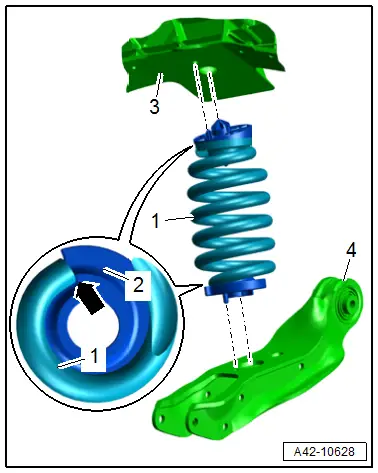
Coil spring and spring plate installation position
- The end of the spring -1- must be positioned to the spring plate -2- until stop -arrow-.
- The positioning pins of the spring plate must engage at the top in the holes in the body -3- and below in the holes in the rear transverse link -4- as shown.
Shock Absorber
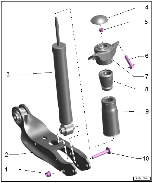
1 - Nut
- 70 Nm +180º
- Replace after removing
- Must be tightened in the curb weight position. Refer to → Chapter "Wheel Bearing at Standard Vehicle Height, Lifting Vehicles with Air Suspension".
2 - Rear Lower Transverse Link
- Removing and installing. Refer to → Chapter "Rear Lower Transverse Link, Removing and Installing".
3 - Shock Absorber
- Because of different shock absorber valve systems, only install new shock absorbers from the same manufacturer on both axles, if possible.
- Removing and installing. Refer to → Chapter "Shock Absorber, Removing and Installing".
4 - Protective Cap
- There are different versions. Refer to the Parts Catalog for the allocation.
5 - Nut
- 35 Nm
6 - Bolt
- 50 Nm +90º
- Replace after removing
7 - Shock Absorber Mount
8 - Spring
9 - Protective Cover
- Installed in the groove on the spring
10 - Bolt
- Replace after removing
Overview - Suspension Strut, Shock Absorber and Spring, Air Spring
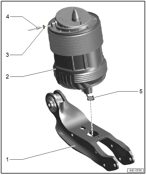
1 - Rear Lower Transverse Link
2 - Air Spring
- Removing and installing. Refer to → Chapter "Spring, Removing and Installing, Air Spring".
- Installation position. Refer to → Fig. "Air Spring Installed Position".
3 - O-Ring
- If sealing ring is leaking nip open and replace.
4 - Air Line
- If the connecting piece is removed separately (without the attached lines) check if the cutting ring has a loose components is still in the threads and if necessary remove.
- Connecting piece tightening specification. Refer to → Chapter "Overview - Air Lines".
5 - Retainer
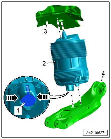
Air Spring Installed Position
- When filling the air suspension system check the installation position of the air suspension system:
- The positioning pins of the air spring -2- must engage at the top in the holes in the body -3- and below in the holes in the rear transverse link -4- as shown.
- The catches in direction of -arrows- must engage audibly in the rear lower transverse link.
- The catches must engage with the retainer -1-.
Shock Absorber
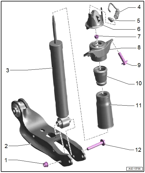
1 - Nut
- Tightening specification. Refer to -item 12-
2 - Rear Lower Transverse Link
- Removing and installing. Refer to → Chapter "Rear Lower Transverse Link, Removing and Installing".
3 - Shock Absorber
- Because of different shock absorber valve systems, only install new shock absorbers from the same manufacturer on both axles, if possible.
- Removing and installing. Refer to → Chapter "Shock Absorber, Removing and Installing".
4 - Connector
5 - Grommet
6 - Protective Cap
7 - Nut
- 35 Nm
8 - Shock Absorber Mount
9 - Bolt
- 50 Nm +90º
- Replace after removing
10 - Spring
11 - Protective Cover
- Installed in the groove on the spring
12 - Bolt
- Replace after removing

