Audi Q7: Relay and Fuse Panels Inside Luggage Compartment on Left Side, Removing and Installing
Fuse Panel F -SF-, Removing and Installing
Removing
- Remove the left luggage compartment side trim panel. Refer to → Body Interior; Rep. Gr.70; Luggage Compartment Trim Panels; Luggage Compartment Side Trim Panel, Removing and Installing.
- Disconnect the connectors -2 and 3-.
- Free up the connector -1-.
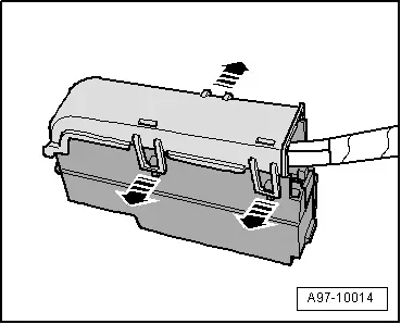
- Release the retainers in direction of -arrow-.
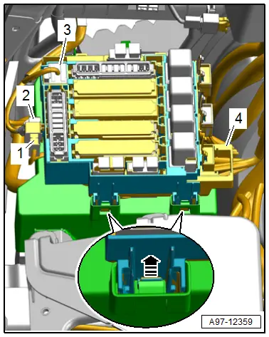
- Lift the fuse panel F -4- and remove to the right.
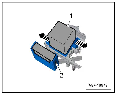
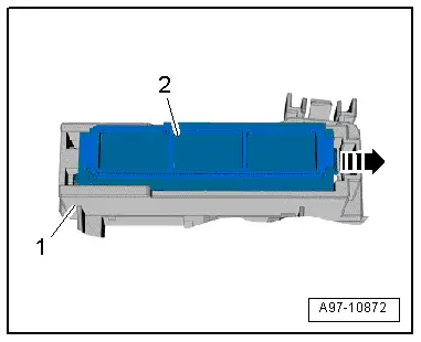
- Open the clip in direction of -arrow- and remove the fuse panel -2- from fuse panel F -1-.

- Open the clip and remove the auxiliary fuse panel -2-.
- Release the clips in direction of -arrows- and remove the relay -1- and the control modules from the relay panels.
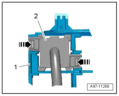
- Open the clips in direction of -arrows- and remove the relay panel -2- from the fuse panel F -1- to the rear.
- Remove fuse panel F.
TIP
Check the exact assignment in the current wiring diagram. Refer to → Wiring diagrams, Troubleshooting & Component locations.
Installing
Install in reverse order of removal.
Tightening Specifications
- Refer to → Chapter "Overview - Component Location Relay Panel, Instrument Panel, E-Boxes, Luggage Compartment"
Fuse Panel F -SF-, Removing and Installing, Vehicles with High-Voltage System
Removing
- Remove the luggage compartment left trim panel. Refer to → Body Interior; Rep. Gr.70; Luggage Compartment Trim Panels; Luggage Compartment Side Trim Panel, Removing and Installing.
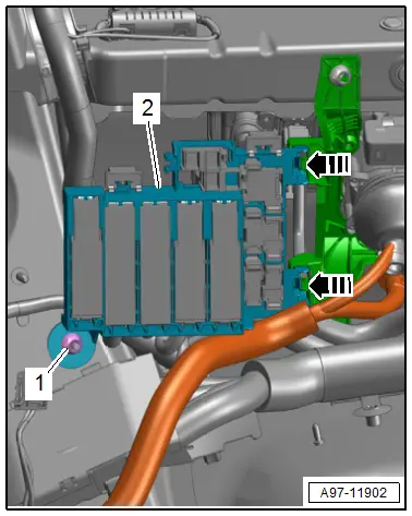
- Remove the nut -1-.
- Release the retainers in direction of -arrows-.
- Remove the fuse panel F -2- to the right.
- Open the clip in direction of -arrow- and remove the fuse panel -2- from fuse panel F -1-.
- Open the clip and remove the auxiliary fuse panel -2-.
- Release the clips in the direction of -arrows- and remove the relay -1- and the control modules from the relay panels.

- Open the clips -arrows- and remove the relay panel -2- from the fuse panel F -1- to the rear.
- Remove fuse panel F.
TIP
Check the exact assignment in the current wiring diagram. Refer to → Wiring diagrams, Troubleshooting & Component locations.

Installing
Install in reverse order of removal.
Tightening Specifications
- Refer to → Chapter "Overview - Component Location Relay Panel, Instrument Panel, E-Boxes, Luggage Compartment"
Left Luggage Compartment Fuse Panel, Removing and Installing
Removing
- Turn off the ignition and disconnect the ground cable from the battery. Refer to → Chapter "Battery, Disconnecting and Connecting".
- Remove the relay and fuse panel F inside the luggage compartment on the left side. The relay mount remains clipped in. Refer to → Chapter "Relay and Fuse Panels Inside Luggage Compartment on Left Side, Removing and Installing".
- Unlock the release and remove it from the fuse panel.
- Remove the fuses from the fuse panel.
- Open the clips in direction of -arrows- and remove the fuse panel cover.
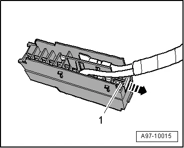
- Pull off retaining strip -1- for the connectors in direction of -arrow- and remove the connectors from the plug-in socket
TIP
Check the exact assignment in the current wiring diagram. Refer to → Wiring diagrams, Troubleshooting & Component locations.
Installing
Install in the reverse order of removal while noting the following:
- Connect the battery. Required actions.
Main Fuse Panel on Battery, Removing and Installing
Removing
- Turn off the ignition and disconnect the ground cable from the battery. Refer to → Chapter "Battery, Disconnecting and Connecting".
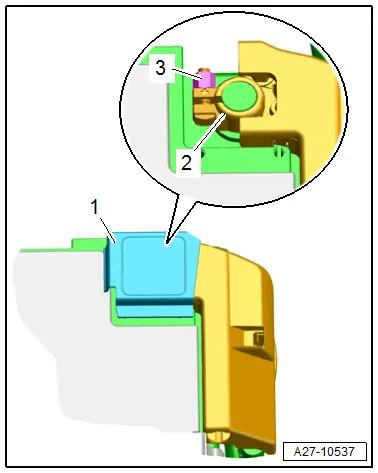
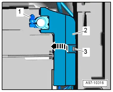
- Open the cover -1- over the battery positive terminal.
- Loosen the nut -3- several turns and remove the battery terminal clamp -2- for the positive cable from the battery terminal.
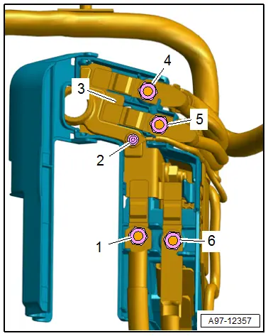
- Release the catch -3- and open the flap -2- above the main fuse panel -1- in direction of -arrow-.
- Remove the wires -1, 2, 4, 5, and 6-.
- Remove the main fuse panel -3-.
TIP
Check the exact assignment in the current wiring diagram. Refer to → Wiring diagrams, Troubleshooting & Component locations.
Installing
Install in the reverse order of removal while noting the following:
- Connect the battery. Required actions.
Tightening Specifications
- Refer to → Fig. "Tightening Specification for the Main Fuse Panel"

