Audi Q7: Roof End Strip, Removing and Installing
Special tools and workshop equipment required
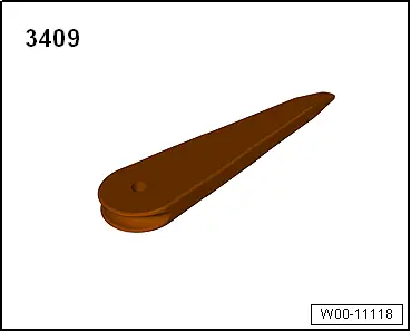
- Trim Removal Wedge -3409-
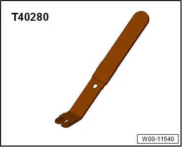
- Omega Clip Tool -T40280-
Removing
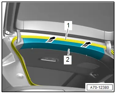
- Free up the roof end strip near the rear lid seal -1-.
- Unclip the roof end strip -2- using the -3409--arrows-.
Installing
Install in reverse order of removal.
Installation notes, for example tightening specifications, replacing components. Refer to → Chapter "Overview - Roof End Strip".
Headliner, Removing and Installing
Special tools and workshop equipment required
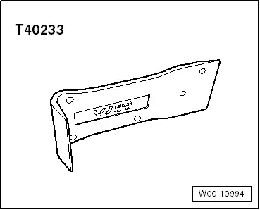
- Removal Wedge -T40233-
Removing
 WARNING
Follow all safety precautions when working on pyrotechnic components. Refer to → Chapter "Safety Precautions for Pyrotechnic Components".
- Remove the A-pillar upper trim panels. Refer to → Chapter "A-Pillar Upper Trim Panel, Removing and Installing".
- Remove the B-pillar upper trim panel on the driver side. Refer to → Chapter "B-Pillar Upper Trim Panel, Removing and Installing".
- Remove the C-pillar trim panel on the driver side. Refer to → Chapter "C-Pillar Trim Panel, Removing and Installing".
- Remove the roof end strip. Refer to → Chapter "Roof End Strip, Removing and Installing".
- Remove the D-pillar trim panel. Refer to → Chapter "D-Pillar Trim Panel, Removing and Installing".
- Remove the front roof module. Refer to → Electrical Equipment; Rep. Gr.96; Controls; Front Interior Lamp/Reading Lamp, Removing and Installing.
- Equipped on some models: remove the front camera cover.
- Remove the sun visors. Refer to → Chapter "Sun Visor, Removing and Installing".
- Remove the sun visor center support. Refer to → Chapter "Sun Visor Center Support, Removing and Installing".
- Remove the roof grab handle. Refer to → Chapter "Roof Grab Handle, Removing and Installing".
Versions with Panorama Roof
- Open the sun shade.
- To prevent dirtying the headliner, clean the -T40233-.
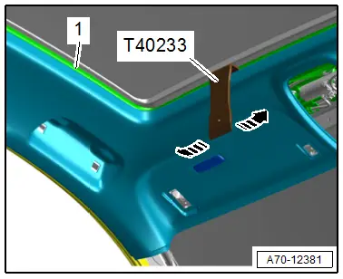
- Push the -T40233- between the frame -1- for the panorama roof and the headliner.
- Loosen the headliner using the -T40233- from the panorama roof frame all the way around -arrows-, as shown.
Continuation for All Vehicles
- Move the front seats into the deepest and most forward position and position the backrest as far toward the front as it will go.
- Fold the rear seat backrests forward.
- Equipped on some models: fold in the third row backrest.
- Free up the headliner in the area near the door seals on the driver side.
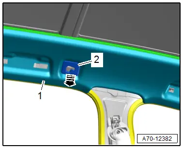
- Unclip the headliner -1- with trim -2- and trim bracket at the screen separator mount in direction of -arrow-.
- Repeat the process on the opposite side.
 Caution
- The headliner bends easily.
- Replace the headliner if it is bent.
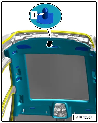
- Grip under the headliner by hand and unclip from the body at the rear of the centering pin -1--arrow-.
 Note
Note
The headliner is removed through the rear lid opening.
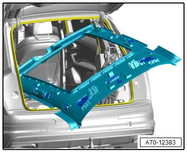
- Lower the headliner on the left side of the vehicle.
- Remove the headliner carefully through the lid opening, as shown in the illustration.
- To do this carefully guide the headliner at the edges through the rear lid opening.
Installing
 WARNING
Follow all safety precautions when working on pyrotechnic components. Refer to → Chapter "Safety Precautions for Pyrotechnic Components".
- Align the headliner, press in the centering pin at the back of the headliner until it engages audibly in the mounting point of the body.
- Install the center support for the sun visor. Refer to → Chapter "Sun Visor Center Support, Removing and Installing".
- Clip the headliner with cover at the mounting eyes.
- Stretch the door seal lip over.
Further installation is the reverse order of removal.
Installation notes, for example tightening specifications, replacing components. Refer to → Chapter "Overview - Headliner".
Roof Reinforcement, Attaching to Body
Special tools and workshop equipment required
- Assembly Adhesive. Refer to the Parts Catalog.
Procedure
- Remove the headliner. Refer to → Chapter "Headliner, Removing and Installing".
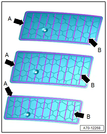
- Apply adhesive beads -arrows- to the roof reinforcement as shown in the illustration.
- Thickness of the beads on the circumference -s- is approximately 7 mm.
- Thickness of the support beads -arrows B- is approximately 5 mm.
- Apply the adhesive beads according to the line markings on the roof reinforcement.
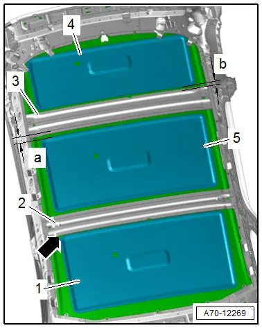
- Mount the roof reinforcement -4- centered to the outer sides and at a distance -b- approximately 15 mm to the bow -1- on the roof.
- Mount the roof reinforcement -5- centered to the outer sides and at a distance -a- approximately 20 mm to the bow -3- on the roof.
- Mount roof reinforcement -1- centered to the outer sides and fitted -arrow- to the bow -2- on the roof.
- Press the roof reinforcement on the roof surface.
- Wipe off any adhesive.
Further installation is the reverse order of removal.
Installation notes, for example tightening specifications, replacing components. Refer to → Chapter "Overview - Headliner".
Special Tools
Special tools and workshop equipment required
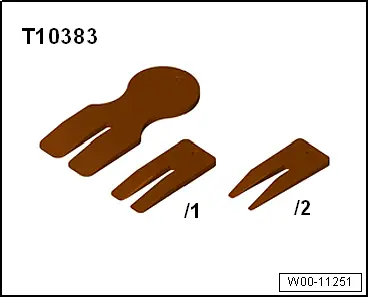
- Wedge Set -T10383-
- Removal Wedge -T40233-
- Omega Clip Tool -T40280-
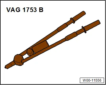
- Pop Rivet Pliers -VAG1753B-
- Trim Removal Wedge -3409-
- Drill
- Drill 3.0 mm diameter, 6.5 mm diameter
- Protective Eyewear