Audi Q7: Timing Chain Cover
Overview - Timing Chain Cover
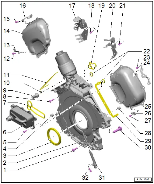
1 - Bolt
- Tightening specification and sequence. Refer to → Fig. "Lower Timing Chain Cover - Tightening Specification and Sequence".
- Replace after removing
2 - Lower Timing Chain Cover
- Removing and installing. Refer to → Chapter "Lower Timing Chain Cover, Removing and Installing".
3 - Gasket
- For the crankshaft on the transmission side
- Replacing. Refer to → Chapter "Crankshaft Seal, Replacing, Transmission Side".
4 - Alignment Sleeve
- Quantity: 2
5 - Bolt
- Tightening specification. Refer to -item 3-
6 - Engine Oil Cooler
- Removing and installing. Refer to → Chapter "Engine Oil Cooler, Removing and Installing".
7 - Seal
- Replace after removing
8 - Bolt
- Tightening specification and sequence. Refer to → Fig. "Lower Timing Chain Cover - Tightening Specification and Sequence".
- Replace after removing
9 - Oil Pressure Switch -F22-
- 20 Nm
- Removing and installing. Refer to → Chapter "Oil Pressure Switch -F22-, Removing and Installing".
- Checking using Vehicle Diagnostic Tester.
- Switching pressure 2.5 to 3.2 bar (36.25 to 46.41 psi)
- Gray insulation
10 - Gasket
- Replace after removing
11 - Left Cylinder Head Gasket
12 - Bolt
- Tightening specification and sequence. Refer to → Fig. "Left Timing Chain Cover - Tightening Specification and Sequence".
- Replace after removing
13 - Bracket
14 - Left Timing Chain Cover
- Removing and installing. Refer to → Chapter "Left Timing Chain Cover, Removing and Installing".
15 - Bolt
- Replace after removing
- Tightening specification and sequence. Refer to → Fig. "Left Timing Chain Cover - Tightening Specification and Sequence".
16 - Bracket
17 - Bracket
- For the connectors for the left heated oxygen sensors
18 - Bolt
- Tightening specification and sequence. Refer to → Fig. "Left Timing Chain Cover - Tightening Specification and Sequence".
19 - Seal
- Replace after removing
20 - Bracket
- For the connectors for the right heated oxygen sensors
21 - Bolt
- Tightening specification and sequence. Refer to → Fig. "Right Timing Chain Cover - Tightening Specification and Sequence".
22 - Seals
- Replace after removing
23 - Bolt
- Tightening specification and sequence. Refer to → Fig. "Right Timing Chain Cover - Tightening Specification and Sequence".
24 - Bracket
- For the connectors
25 - Right Timing Chain Cover
- Removing and installing. Refer to → Chapter "Right Timing Chain Cover, Removing and Installing".
26 - Bracket
27 - Bolt
- Replace after removing
- Tightening specification and sequence. Refer to → Fig. "Right Timing Chain Cover - Tightening Specification and Sequence".
28 - Alignment Sleeve
- Quantity: 2
29 - Right Cylinder Head Gasket
30 - Bolt
- Tightening specification and sequence. Refer to → Fig. "Lower Timing Chain Cover - Tightening Specification and Sequence".
31 - Engine Speed Sensor -G28-
- Removing and installing. Refer to → Chapter "Engine Speed Sensor -G28-, Removing and Installing".
32 - Bolt
- Tightening specification. Refer to -item 11-
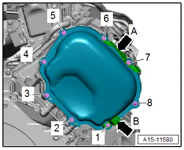
Left Timing Chain Cover - Tightening Specification and Sequence
 Note
Note
- Replace the bolts that were tightened with an additional turn after removing them.
- The brackets -A and B arrows- are attached to the left timing chain cover.
- Item -8- is a double bolt.
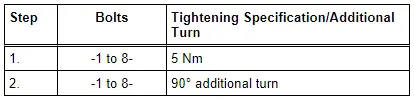
- Tighten the bolts in the steps of the sequence shown:
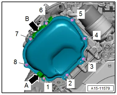
Right Timing Chain Cover - Tightening Specification and Sequence
 Note
Note
- Replace the bolts that were tightened with an additional turn after removing them.
- The brackets -A and B arrows- are attached to the right timing chain cover.
- Item -8- is a double bolt.
- Tighten the bolts in the steps of the sequence shown:
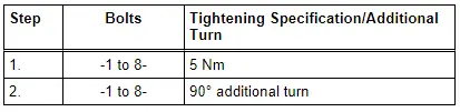
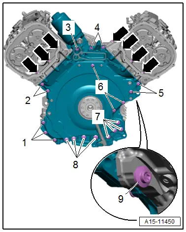
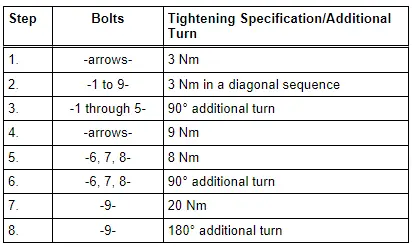
Lower Timing Chain Cover - Tightening Specification and Sequence
 Note
Note
Replace the bolts that were tightened with an additional turn after removing them.
- Tighten the bolts in stages as follows: