Audi Q7: Transmission Control
Audi Q7 (4M) 2016-2026 Workshop Manual / Transmission / Rear Final Drive, Differential / Transmission Control
Component Location Overview - Transmission Control
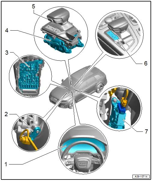
1 - Instrument Cluster
- With Instrument Cluster Control Module -J285-
- Overview. Refer to → Electrical Equipment; Rep. Gr.90; Instrument Cluster; Overview - Instrument Cluster.
2 - Brake Lamp Switch -F-
- Overview. Refer to → Brake System; Rep. Gr.47; Brake Booster/Brake Master Cylinder; Overview - Brake Booster/Brake Master Cylinder
3 - Mechatronic
- With hydraulic pulse memory
- The following components are integrated in the Mechatronic:
- Transmission Control Module -J217-
- Solenoid Valve 1 -N88-
- Automatic Transmission Pressure Regulating Valve 1 -N215-
- Automatic Transmission Pressure Regulating Valve 2 -N216-
- Automatic Transmission Pressure Regulating Valve 3 -N217-
- Automatic Transmission Pressure Regulating Valve 4 -N218-
- Automatic Transmission Pressure Regulating Valve 5 -N233-
- Automatic Transmission Pressure Regulating Valve 6 -N371-
- Automatic Transmission Pressure Regulating Valve 7 -N443-
- Accumulator Solenoid -N485-
- Parking Lock Solenoid -N486-
- Transmission Fluid Temperature Sensor -G93-
- Transmission Input Speed Sensor -G182-
- Transmission Output Speed Sensor -G195-
- Temperature Sensor In Control Module -G510-
- Parking Lock Sensor -G747-
- The components cannot be replaced separately if faulty.
- OBD checks all components.
- Overview. Refer to → Chapter "Overview - ATF System".
4 - Selector Mechanism
- The following components are integrated in the selector mechanism
- Selector Lever -E313-
- Selector Lever Position Sensor -G727-
- Transverse Selector Lever Lock Sensor -G868-
- Selector Lever Sensor System Control Module -J587-
- Shift Lock Solenoid -N110-
- Transverse Selector Lever Lock Motor -V577-
- The components cannot be replaced separately if faulty.
- Overview. Refer to → Chapter "Overview - Selector Mechanism".
5 - Selector Lever Handle
- The following components are integrated in the selector mechanism
- Selector Lever Release Button -E681-
- Parking Lock Button -E816-
- The components cannot be replaced separately if faulty.
- Overview. Refer to → Chapter "Overview - Selector Mechanism".
- 6 - Selector Lever Transmission Range Display -Y5-
- Removing and installing. Refer to → Electrical Equipment; Rep. Gr.96; Lamps; Component Location Overview - Center Console Lamps.
7 - Kick Down Switch
- A specific value from accelerator pedal module with the Accelerator Pedal Position Sensor -G79-/Accelerator Pedal Position Sensor 2 -G185- is stored in the engine control module.
- Accelerator pedal module, removing and installing. Refer to → Rep. Gr.20; Accelerator Mechanism; Accelerator Pedal Position Sensors G79/G185, Removing and Installing.
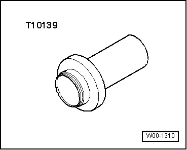
Special Tools
Special tools and workshop equipment required
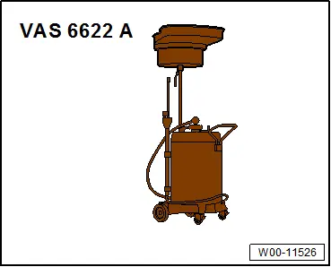
- Used Oil Collection and Extraction Unit -SMN372500-
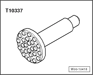
- Engine/Gearbox Jack - Gearbox Support -T10337-
- Engine/Gearbox Jack - Gearbox Support -T10337-
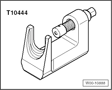
- Ball Joint Removal Tool -T10444-
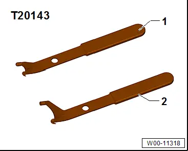
- Puller - Crankshaft/Power Steering Seal -T20143/1-
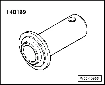
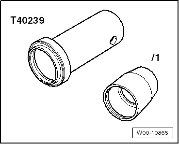
- Seal Installer - Flange Seal -T40189-
- Seal Installer - Output Shaft -T40239-
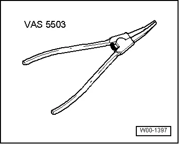
- Circlip Pliers -VAS5503A-
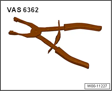
- Hose Clip Pliers -VAS6362-
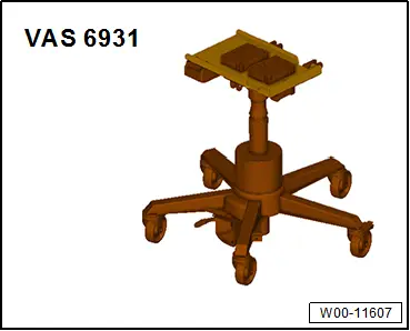
- Engine and Gearbox Jack -VAS6931-
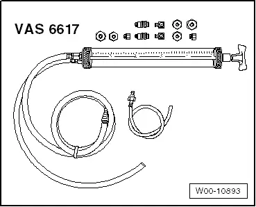
- Pressurized Gearbox Oil Filler Kit -VAS6617-
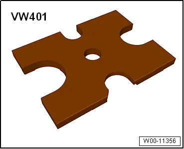
- Press Plate -VW401-
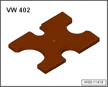
- Press Plate -VW402-
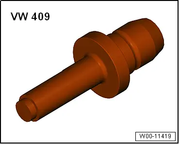
- Press Piece - Rod -VW409-
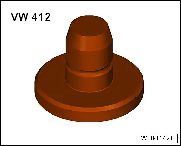
- Press Piece - Multiple Use -VW412-
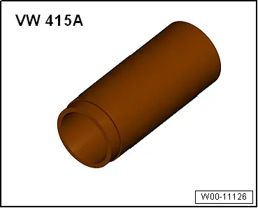
- Press Piece - 60mm -VW415A-
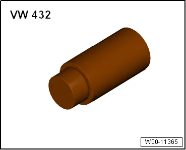
- Press Piece - Bushing - 50mm Diameter -VW432-
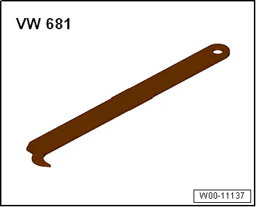
- Puller - Seal Lever -VW681- or Puller - Crankshaft/Power Steering Seal -T20143/2-
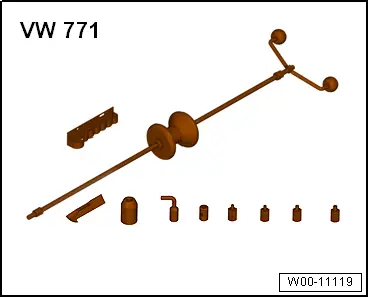
- Slide Hammer Set -VW771- with Slide Hammer Set - Bolt -VW771/43-
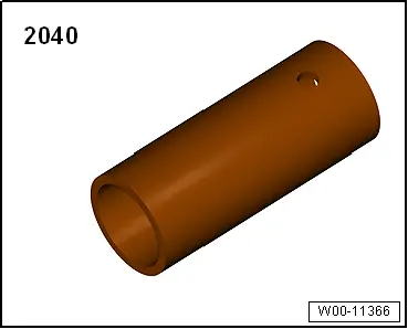
- Press Piece - Front Control Arm -2040-
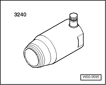
- Puller - Camshaft Seal -3240-
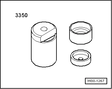
- Bearing Installer - Carrier Bearing -3350-
- Splitter VAS251 411 -VAS251411-
Revision History
DRUCK NUMBER: A005A010321