Audi Q7: Vacuum System
Connection Diagram - Vacuum System
 Caution
There is a risk that an engine malfunction may occur.
When routing the vacuum lines, make sure they are not kinked, twisted or pinched.
 Note
Note
- Dark gray - vacuum supply line
- Red = control line to the intake manifold runner control vacuum actuator.
- Pink - Control line to the secondary air injection combination valve.
- Green - Control line to the coolant shut-off valve.
- Light gray - control line to the coolant pump.
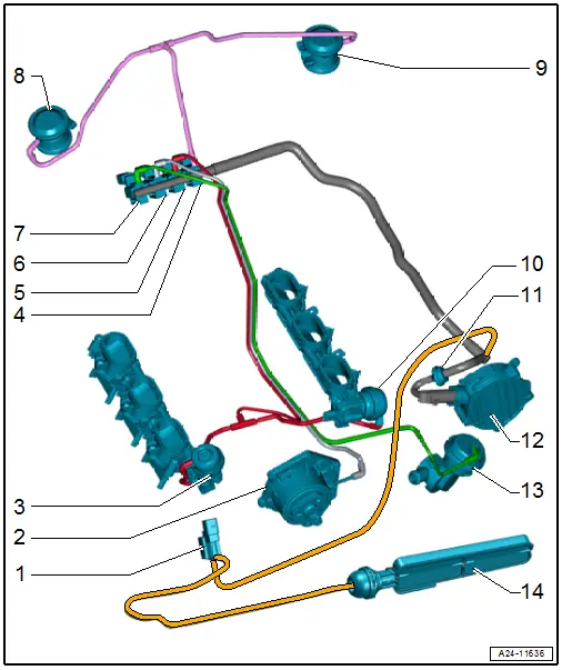
1 - Air Filter Bypass Door Valve -N275-
2 - Coolant Pump
3 - Vacuum Diaphragm
- For intake manifold flap at cylinder bank 1 (right)
4 - Secondary Air Injection Solenoid Valve -N112-
5 - Intake Manifold Runner Control Valve -N316-
6 - Cylinder Head Coolant Valve -N489-
7 - Cooling Circuit Solenoid Valve -N492-
8 - Right Secondary Air Injection Combination Valve
9 - Left Secondary Air Injection Combination Valve
10 - Vacuum Diaphragm
- For intake manifold flap at cylinder bank 2 (left)
11 - Check Valve
12 - Vacuum Pump
13 - Coolant Shut-Off Valve
14 - Air Filter Bypass Door
Vacuum System, Checking
Special tools and workshop equipment required
- Hand Vacuum Pump -VAS6213-
Procedure
- Check all vacuum lines in the entire vacuum system for:
- Cracks
- Damage caused by animals
- Pinching
- Porous locations and other leaks
- Check the vacuum line leading both to and from the solenoid valve to the respective component.
- If there is a fault stored in the DTC memory, check the vacuum lines for the named component, but also check all the vacuum lines.
- If using the Hand Vacuum Pump -VAS6213- does not produce any vacuum or if the vacuum drops again right away, then check the hand vacuum pump and the connection hoses for leaks.

