Audi Q7: Intake and Exhaust Valves
Audi Q7 (4M) 2016-2026 Workshop Manual / Engine / 6-Cylinder Direct Injection 3.0L 4V TFSI Supercharged Engine / Cylinder Head, Valvetrain / Intake and Exhaust Valves
Valve Guides, Checking
Special tools and workshop equipment required
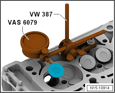
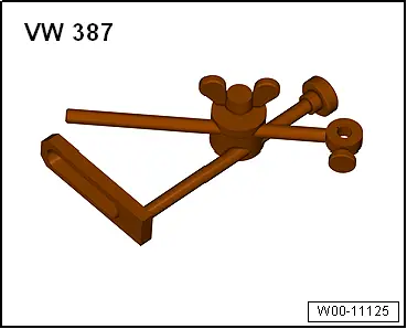
- Dial Gauge Holder -VW387-
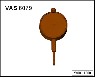
- Dial Gauge - 0-10mm -VAS6079-
Procedure
 Note
Note
- If the valve is replaced during repair, use the new valve for measurement.
- Due to different stem diameters, only use an intake valve in the intake valve guide and an exhaust valve in the exhaust valve guide.
- Secure the Dial Gauge - 0-10mm -VAS6079- on the cylinder head with the Dial Gauge Holder -VW387- as shown in the illustration.
- Place the valve in the valve guide.
- Valve stem tip must seal with the valve guide.
- Determine the tilting clearance.
- Wear limit: 0.8 mm.
- If the wear limit is exceeded, measure using new valves.
- Replace the cylinder head if the wear limit is still exceeded.
 Note
Note
The valve guides cannot be replaced.
Valves, Checking
- Check the valves at stem and seat surface for wear grooves.
- If there are clear wear grooves, replace the valve.
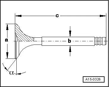
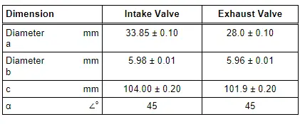
Valve Dimensions
 Note
Note
Intake and exhaust valves must not be reworked. Only lapping is permitted.
Special Tools
Special tools and workshop equipment required
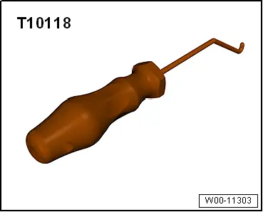
- Elbow Assembly Tool -T10118-
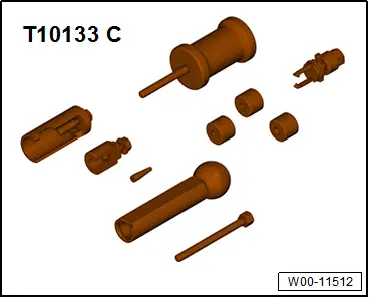
- Injector/Combustion Chamber Seal Tool Set - Impact Puller -T10133/3- from Injector/Combustion Chamber Seal Tool Set -T10133C-
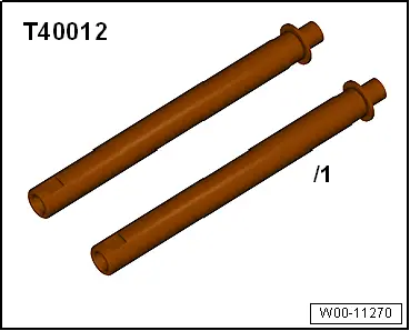
- Valve Cotter Tool Kit - Adapter -T40012-
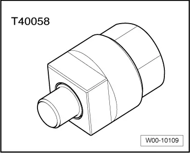
- Crankshaft Socket -T40058-
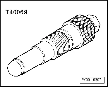
- Crankshaft Locking Pin -T40069-
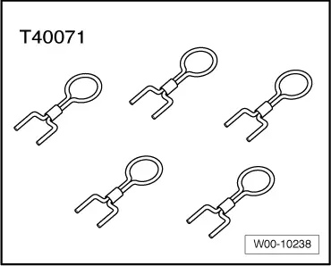
- Locking Pin -T40071- (quantity: 2)
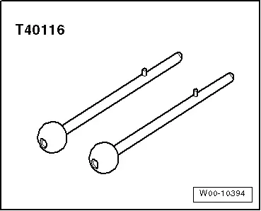
- Locating Pins -T40116-
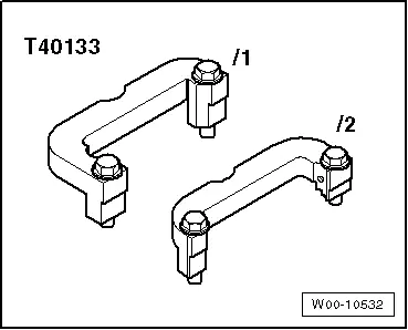
- Camshaft Clamp -T40133- (quantity: 2)
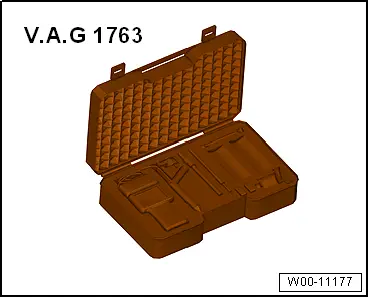
- Compression Tester Kit -VAG1763-
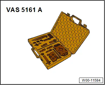
- Valve Keeper Tool Kit -VAS5161A- with the Valve Cotter Tool Kit - Guide Plate 19C -VAS5161/19C-
- Dial Gauge - 0-10mm -VAS6079-
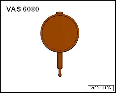
- Dial Gauge - 0-3mm -VAS6080-
- Engine and Gearbox Bracket -VAS 6095A-
- Engine Bung Set -VAS6122-
- Cylinder Head Tensioning Device -VAS6419-
- Dial Gauge Holder -VW387-
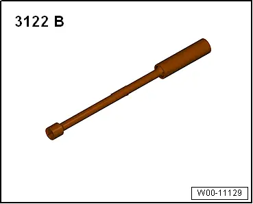
- Spark Plug Removal Tool -3122B-
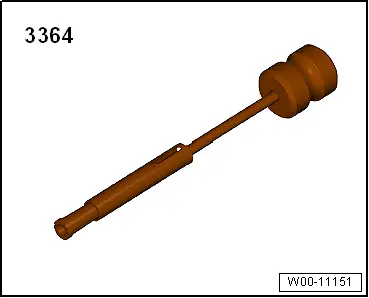
- Puller - Valve Seal -3364-
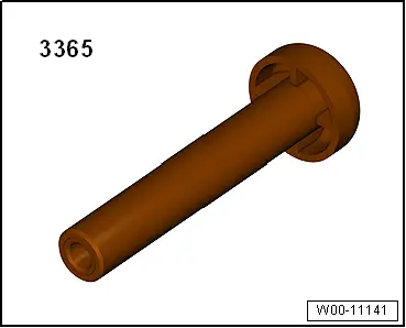
- Seal Installer - Valve Stem -3365-
- Timing Chain Tensioning Key -T40297-