Audi Q7: Windshield
Overview - Windshield
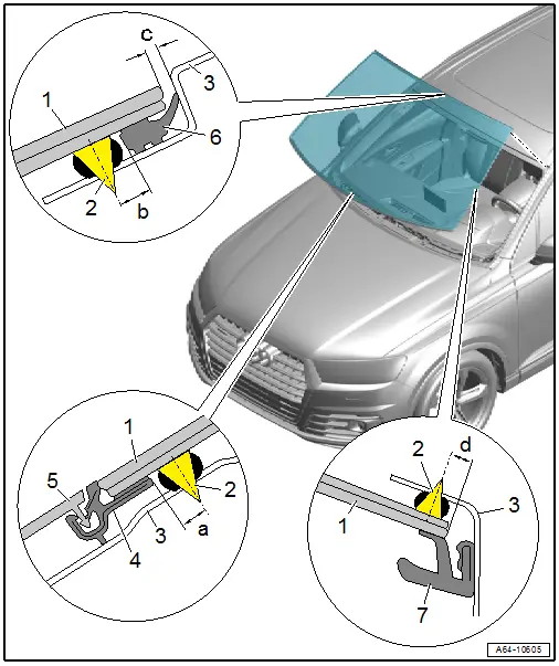
1 - Windshield
- Distance to roof frame: dimension -c- = 2.5 mm
- Center the side distance to the A-pillars
2 - Adhesive Bead
- Observe the minimum curing time. Refer to → Chapter "Minimum Curing Times for Bonded Windows".
- Note the different spacing dimensions to window edge
- Dimension -a- = 6 mm
- Dimension -b- = 7 mm
- Dimension -d- = 6 mm
- Adhesive bead thickness.
3 - Roof Frame
4 - Plenum Chamber Cover Frame
- No replacement part
- With a new window glass remove the protective piping. Refer to → Fig.
5 - Plenum Chamber Cover
- Only press into retaining strip after window adhesive minimum curing time is complete (two hours).
- Remove the protective piping before assembling. Refer to → Fig.
- Removing and Installing. Refer to → Chapter "Plenum Chamber Cover, Removing and Installing".
6 - Molding
- Must not be damaged in the visible area
7 - Drip Rail
- Removing and Installing. Refer to → Chapter "Drip Rail, Removing and Installing".
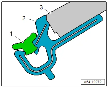
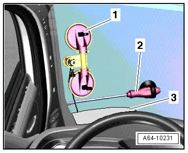
Protective Molding, Removing
- For a new windshield -3-, the protective molding -1- must first be removed from the frame -2- before assembling the plenum chamber cover.
Windshield, Removing and Installing
- Follow repair instructions. Refer to → Chapter "Repair Information".
- Depending on the equipment version, the following additional work must be performed.
- Necessary Tools and Materials for Removing and Installing. Refer to → Chapter "Necessary Tools and Materials for Removing and Installing".
Removing
- Remove the left and right drip rail. Refer to → Chapter "Drip Rail, Removing and Installing".
- Remove the windshield wiper arms. Refer to → Electrical Equipment; Rep. Gr.92; Windshield Wiper System; Windshield Wiper Arms, Removing and Installing.
- Remove the plenum chamber cover. Refer to → Chapter "Plenum Chamber Cover, Removing and Installing".
- Remove the left and right sun visor. Refer to → Body Interior; Rep. Gr.68; Equipment; Overview - Sun Visors.
- Remove the front interior lamp/reading lamp. Refer to → Electrical Equipment; Rep. Gr.96; Controls; Front Interior Lamp/Reading Lamp, Removing and Installing.
- Remove the left and right front roof grab handle. Refer to → Body Interior; Rep. Gr.68; Equipment; Roof Grab Handle, Removing and Installing.
- Remove the interior rearview mirror. Refer to → Body Interior; Rep. Gr.68; Interior Rearview Mirror; Interior Rearview Mirror, Removing and Installing.
- Remove the driver assistance systems front camera. Refer to → Electrical Equipment; Rep. Gr.96; Driver Assistance Systems Front Camera; Driver Assistance Systems Front Camera, Removing and Installing.
- Remove the rain/light recognition sensor. Refer to → Electrical Equipment; Rep. Gr.92; Windshield Wiper System; Rain/Light Recognition Sensor, Removing and Installing.
- Remove the left and right A-pillar trim panels. Refer to → Body Interior; Rep. Gr.70; Vehicle Interior Trim Panels; A-Pillar Trim Panel, Removing and Installing.
 WARNING
Risk of injury to the hands and eyes from glass fragments.
Getting cut is possible.
- Wear protective eyewear.
- Wear safety gloves.
- Unroll approximately 6.5 meters of cutting wire (approximately six turns) with the -VAS6452/1- and cut it.
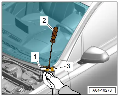
- To prevent any damage, cover the area where the awl comes out at the bottom of the body flange with adhesive tape -1-.
- Working from the inside outward, pierce the adhesive bead in this area using the awl -2-.
- Thread both cutting wire ends -3- into the awl and pull it toward the inside.
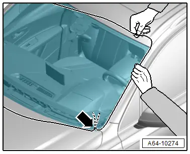
- Place the cutting wire all the way around under the windshield.
- The wire ends must not be twisted on the adhesive bead pass-through -arrow-.
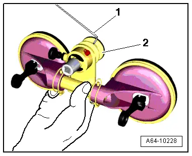
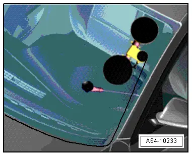
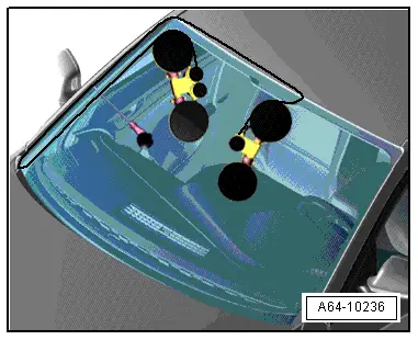
- Mount both reel devices on the inside of the windshield as shown.
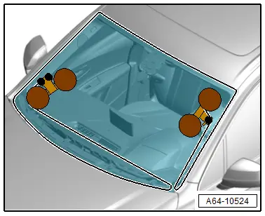
- Insert the cutting wire end -1- into the reel device -2-.
- Tension the cutting wire with the reel device -1- and push the protective film -2- between the instrument panel and the wire.
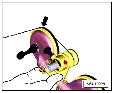
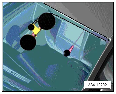
- Cut free the first section, while doing this, the wire is guided into the integrated idler roller -arrow- from the reel device.
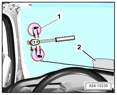
- Insert an additional guide awl -2- into the adhesive bead and secure it to the windshield with the suction cup as shown to make sure that the wire runs as close to the windshield as possible.
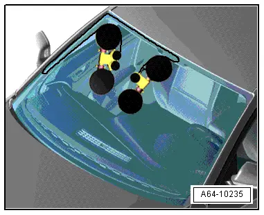
- If necessary, move the protective film -3- along with the wire and cut the window glass free with the reel device -1-.
- Cut free the area on the A-pillar.
- Move the reel device and guide awl as shown, up to approximately the center of the windshield.
- Cut the window glass free up to the center of the glass.
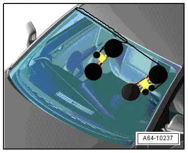
- Use the second reel device to cut the lower section of the window glass free.
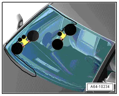
- Move the reel device upward as shown and insert the guide awl.
- Cut the window glass out by moving upward along the A-pillar.
- Move the reel device over the center of the window and in the first reel device as shown.
- Completely cut free the windshield at the upper edge.
- Remove the windshield from the vehicle with two suction lifters.
Installing
- Prepare the undamaged window glass for installing. Refer to → Chapter "Undamaged Window Glass, Preparing for Installation".
- Prepare the new window glass for installation. Refer to → Chapter "New Window Glass, Preparing for Installation".
- Prepare the body flange for installation. Refer to → Chapter "Body Flange, Preparing for Installation".
- Insert the windshield into the window opening using two suction lifters and align it on the sides.
- Distance from the window edge to the roof frame → Chapter "Overview - Windshield".
- Secure the window to the top of the roof with adhesive tape.
- Before installing the plenum chamber cover, first remove the protective profile from the frame. Refer to → Fig.
- Observe minimum curing times. Refer to → Chapter "Minimum Curing Times for Bonded Windows".
Further installation is performed in reverse order of removal, while noting the following:
- Versions with driver assistance systems front camera: recalibrate the camera. Refer to → Suspension, Wheels, Steering; Rep. Gr.44; Driver Assistance Systems Front Camera; Driver Assistance Systems Front Camera, Calibrating.
- Versions with Matrix LED headlamp: calibrate the Matrix LED headlamp. Refer to → Electrical Equipment; Rep. Gr.94; Headlamp.

