Audi Q7: Air Line, Servicing
 Note
Note
- Both rear axle air lines (blue and black) are completely replaced if there is a damage claim. The repair of a damaged line is not permitted.
- The front axle and pressure reservoir air lines are routed in the wiring harness and can be repaired.
Special tools and workshop equipment required
- Torque Wrench 1783 - 2-10Nm -VAG1783-
- Torque Wrench 1783 - Open Jaw - 10mm -VAG1783/1-
- Hose Cutting Pliers -VAS6228-
- Air line repair kit. Refer to the Parts Catalog.
Repair 1
- The damaged point of the air line in the wiring harness is not larger than the coupling itself and is not located in a bend of the line routing.
- Free up the corresponding air line from the wiring harness.
- Remove the damaged location.
- Connect the ends of the original line with a coupling from the repair kit.
- Rebundle the wiring harness after servicing.
Repair 2
- The damaged point of an air line in the wiring harness is larger than the coupling itself.
- Open the wiring harness at the damaged location.
- Remove the faulty section of the air line.
- Starting at the solenoid valve block, suspension strut or pressure reservoir route the repair piece parallel to the original wiring harness.
- Connect the ends of the lines with a coupling from the repair kit.
 Note
Note
To prevent leaks, the air line in front of and behind the coupling must run straight to a length of 100 mm.
Procedure
 Note
Note
- For each line a maximum of two repairs is permitted.
- For a connected wiring harnesses only one repair location each is permitted.
- The position of the repair location must be documented and supplied in the vehicle.
- Clean separation point area before disconnecting air line connector.
- Contaminants entering the lines can lead to system malfunction.
- Clean the area on the connecting piece on the corresponding separation point. Refer to → Chapter "Overview - Air Lines" for the separation point overview.
- Cut through the air line at a right angle at the connector area using Hose Cutting Pliers -VAS6228-.
- Remove connector piece and air line.
- Mark ends of air line in the vehicle and both ends of new air line with a waterproof pen.
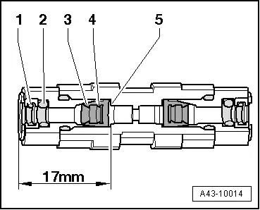
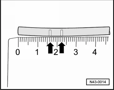
- With "17 mm" or "22 mm" marks, it is checked whether the connector piece is inserted far enough in air line.
- Place the foam rubber on both line.
- Install a new line connector.
 Note
Note
Connector pieces in line connector are already tightened to proper torque. Air lines only have to be connected.
- Remove transport protection cap.

- Push the old air line through the sealing rings -1 and 2-.
- Then slide the air line with some force through edges -3 and 4- of cutting rings as far as stop -5- in line connector.
- Push the foam rubber on the connecting pieces.
- Repeat the procedure with the new air line.
- Connecting piece, replacing. Refer to → Chapter "Connecting Piece, Replacing".
Separating Point: Air Line for the Left Front Air Spring
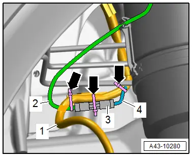
- Loosen the original air line -4- from the wiring harness -1-.
- Surround the wiring harness properly.
- Service the air line.
- Attach the wiring connector -3- and the new air line -2- to the wiring harness with cable ties -arrows-.
Separating Point: Air Line for the Right Front Air Spring
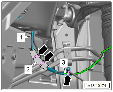
- Service the air line -1-.
- Secure the coated wiring connector -2- and new air line -3- with cable ties -arrows- on the brake line.
Rear Air Line and Front Air Spring Separating Point
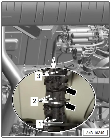
- Loosen the original air lines -1- from the wiring harness.
- Surround the wiring harness properly.
- Service the air line.
- Attach the wiring connector -2- and the new air lines -3- to the wiring harness with cable ties -arrows-.
 Note
Note
A repair with multiple repair locations is shown.
Tightening Specifications
- -Item 5-
Connecting Piece, Replacing
Special tools and workshop equipment required
- Torque Wrench 1783 - 2-10Nm -VAG1783-
- Torque Wrench 1783 - Open Jaw - 10mm -VAG1783/1-
- Hose Cutting Pliers -VAS6228-
Procedure
If connector leaks, if air line is long enough, it can be shortened by 10 mm and a new connecting piece installed.
 Note
Note
- Replace the connecting piece after removing
- Clean separation point area before disconnecting air line connector.
- Contaminants entering the lines can lead to system malfunction.
- Remove connector piece and air line.
- Remove cutting ring from air line.
- Using the Hose Cutting Pliers -VAS6228-, cut the air line behind the pressure point from cutting ring at right angle.
- Mark the air line ends of the air line in the vehicle with a waterproof felt-tip marker.
 Note
Note
With 17 mm or 22 mm marks, it is checked whether the connector piece is inserted far enough in air line.
- Install new connecting piece by hand and tighten.
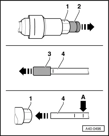
- Only remove the transport protection caps -2 and 3- after connecting air line -4-.
- Route the air line with the applicable clips/grommets in the vehicle. If necessary replace the cut cable tie.
- Remove the transport protection caps.
- Slide air line -4- in with some force as far as stop in connector piece -1-.
- Air lines are installed correctly when only one of the two markings is visible -arrow A-.
Tightening Specifications
- Refer to → Chapter "Overview - Air Lines"
Air Supply Unit, Removing and Installing
Air Supply Unit with Bracket, Removing and Installing
Special tools and workshop equipment required
- Torque Wrench 1783 - 2-10Nm -VAG1783-
- Torque Wrench 1783 - Open Jaw - 10mm -VAG1783/1-
Removing
 Note
Note
Follow the guidelines for clean working conditions. Refer to → Chapter "Guidelines for Clean Working Conditions".
- Vent the system. Refer to → Chapter "Air Suspension System, Filling and Bleeding".
- Switch off the ignition.
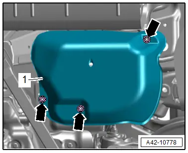
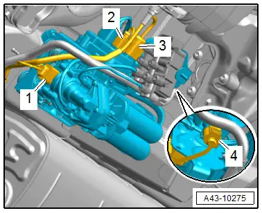
- Remove the nuts -arrows-, and remove the cover -1- for the air supply unit.
- Disconnect the connector -3- from the solenoid valve -1-.
- Remove the air lines -arrows- and protect them from dirt.
 Note
Note
Ignore -2-.
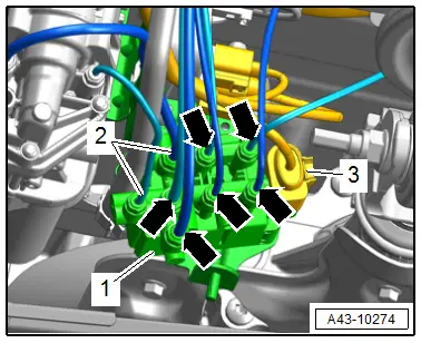
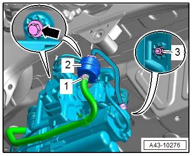
- Disconnect the connectors -1, 2 and 3-.
- Free up the wiring harness.
 Note
Note
Ignore item -4-.
- Loosen the clamp -1- and remove the intake air guide from the air filter -2- and free it up.
- Remove the bolt -arrow- and nut -3- and remove the bracket with the air supply unit.
Installing
Install in reverse order of removal and note the following:
- Fill the system. Refer to → Chapter "Air Suspension System, Filling and Bleeding".
Tightening Specifications
- Refer to → Chapter "Overview - Air Supply Unit"
Air Supply Unit, Removing and Installing
Special tools and workshop equipment required
- Torque Wrench 1783 - 2-10Nm -VAG1783-
Removing
 Note
Note
Follow the guidelines for clean working conditions. Refer to → Chapter "Guidelines for Clean Working Conditions".
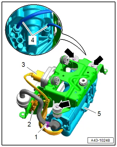
- Disconnect the connector -3- and free up the wire.
- If equipped, remove the connector -2- from the bracket and free it up.
- Remove the air lines -4- from the solenoid valve.
- Loosen the clamp -1- and remove the intake line.
- Remove the bolts -arrows- and remove the air supply unit -5-.
Installing
Install in reverse order of removal.
Tightening Specifications
- Refer to → Chapter "Overview - Air Supply Unit"

