Audi Q7: Overview - Door
Overview - Door
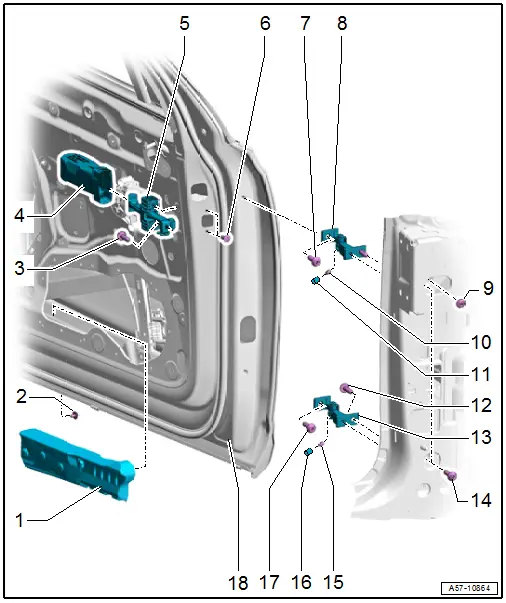
1 - Protective Padding
- Installing. Refer to → Fig.
2 - Bolt
- 3 Nm
3 - Bolt
- 33 Nm
4 - Cap
- For the door arrester
- Installation position. Refer to → Fig.
5 - Door Arrester
- Installation position. Refer to → Fig.
- Removing and Installing. Refer to → Chapter "Door Arrester, Removing and Installing".
6 - Bolt
- 8 Nm
- Replace after removing
- Quantity: 2
7 - Bolt
- 45 Nm
8 - Upper Door Hinge
9 - Nut
- 32 Nm
10 - Set Screw
- 23 Nm
11 - Cap
12 - Bolt
- 32 Nm
13 - Lower Door Hinge
14 - Bolt
- 32 Nm
15 - Set Screw
- 23 Nm
16 - Cap
17 - Bolt
- 45 Nm
18 - Door
- Removing and Installing. Refer to → Chapter "Door, Removing and Installing".
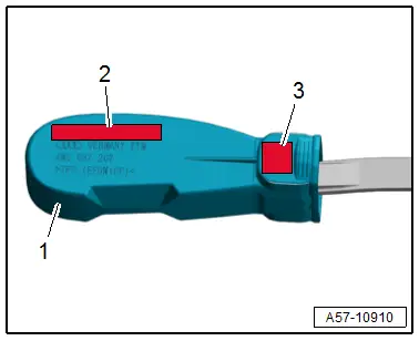
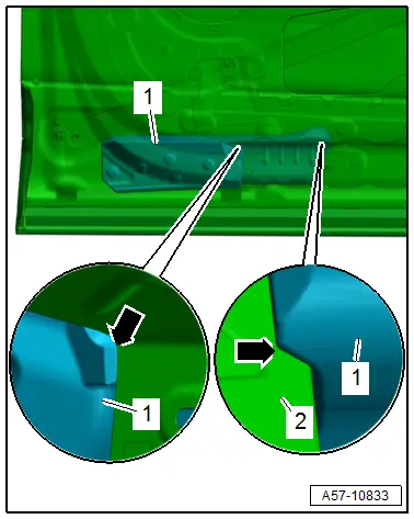
Cap Installation Position
- In the installed position, the lettering on the cap -1- must be readable in the upper installation position.
2 - LEFT UPPER FRONT - left / RIGHT UPPER FRONT - right
3 - VL - left / VR - right
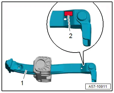
Door Arrester Installation Position
- In the installed position, the lettering on the door arrester -1- must be readable in the upper installation position:
2 - VL - left / VR - right
Protective Padding, Installing
 Note
Note
When installing a new door, the protective padding -1- must be installed in the painted unfinished door.
- Remove the protective film from the adhesive tape -arrows- on the protective padding.
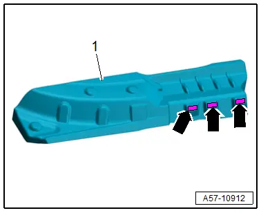
- Bring the protective padding -1- through the opening for the bass box into the installation position.
- The protective padding must contact the door panel reinforcement -2--arrows-.
- Install the bolts -arrows- in the threaded pins -1- from the protective padding -2- and tighten.
Tightening Specifications
- Refer to → Chapter "Overview - Door"
Overview - Impact Member
1 - B-Pillar Cover
2 - Bolt
- 8 Nm
3 - Member Plate
4 - Impact Member
- Market-Specific Version
- Removing and Installing. Refer to → Chapter "Impact Member, Removing and Installing".
5 - Door
6 - A-Pillar Cover
7 - Bolt
- 8 Nm
- Quantity: 4
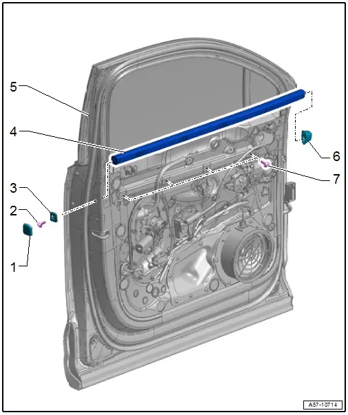
Overview - Door Seals
1 - Seam Seal
- Replace after removing
- Removing and Installing. Refer to → Chapter "Seam Seal, Removing and Installing".
2 - Outer Door Seal
- Replace after removing
- Installation position. Refer to → Fig.
- Removing and Installing. Refer to → Chapter "Outer Door Seal, Removing and Installing".
3 - Inner Door Seal
- Removing and Installing. Refer to → Chapter "Inner Door Seal, Removing and Installing".
4 - B-Pillar Seal
- Installation position. Refer to → Fig.
5 - Door
- Removing and Installing. Refer to → Chapter "Door, Removing and Installing".
B-Pillar Seal Installation Position
- The vehicle and the seal must be at room temperature.
- The adhesive surfaces must be free of dirt and grease.
- If the Bonding Agent -D 355 205 A2- dries longer than 3 hours, then it must be primed again.
- Clean the adhesive surface using the Cleaning Solution -D 009 401 04-.
- Apply Bonding Agent -D 355 205 A2- on the adhesive surface using the Applicator -D 009 500 25- and let dry.
- Remove the protective film, bring the seal in the installation position and apply it:
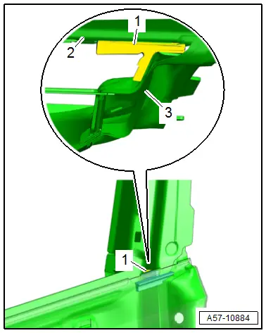
1 - Seal
2 - Outer Door Panel
3 - Inner Door Panel
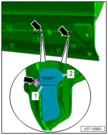
Outer Door Seal Installation Position
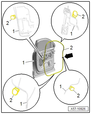
1 - Door Body
2 - Outer Door Seal
- Position the outer door seal with the vulcanized point -arrow- centered to the opening for the door arrester on the door body.

