Audi Q7: Door, Removing and Installing
Removing
- Disconnect the door cut-off connector -1- from the A-pillar. Refer to → Electrical Equipment; Rep. Gr.97; Connectors.
- Tape off the A-pillar in the door arrester area using adhesive tape, so that the paint will not be damaged.
- Remove the door arrester bolt -2-.
- Remove the upper and lower cap -3-.
- Remove the set screw -4- from the top and bottom of the door hinge.
- Carefully remove the door upward out of the door hinges.
Installing
Install in reverse order of removal and note the following:
- Do not make any adjustments after installing the front door.
Tightening Specifications
- Refer to → Chapter "Overview - Door"
Door, Adjusting
Adjustment Dimensions
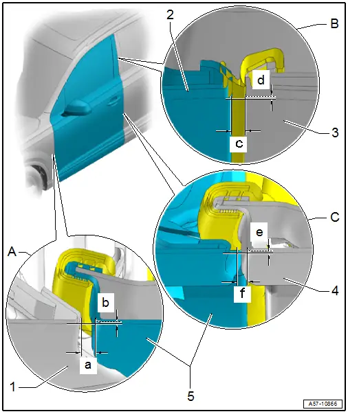
A - Front Door to Fender
- Gap dimension -a- = 3.4 +- 0.5 mm
- Flush dimension -b- = 0/-1.0 mm
- Parallel alignment = 0.5 mm
-1- Front fender
-5- Front door
B - Front Door to Top of Rear Door
- Gap dimension -c- = 3.8 +- 1.0 mm
- Flush dimension -d- = 0.5/-1.0 mm
- Parallel alignment = 0.5 mm
-2- Front B-Pillar Trim
-3- Rear B-Pillar Trim
C - Front Door to Bottom of Rear Door
- Gap dimension -f- = 4.0 -0.3/+0.7 mm
- Flush dimension -e- = 0/- 1.0 mm.
- Parallel alignment = 0.5 mm
-4- Rear Door
-5- Front door
Door Adjustment, Checking
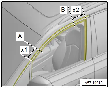
Check Points for Adjusting Door, Using -T40038/18-.
Check the height and side adjustment at check point "A" using -T40038/18-.
Check the height and side adjustment at check point "B" using -T40038/18-.
-
Adjustment dimensions. Refer to → Chapter "Adjustment Dimensions".
Special tools and workshop equipment required
- Gauge - Gap Adjustment -3371-
- Template -T40038/18-
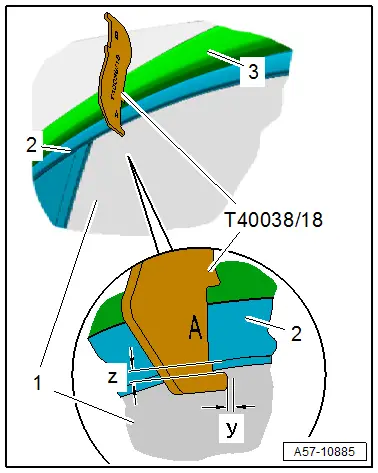
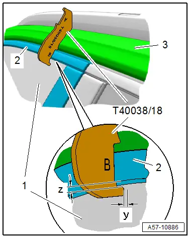
Check Points for Adjusting Door, Using -T40038/18-
- Place the template on the check point:
- Template side "A" on the check point -A- at distance -x1- = 150 mm.
- Template side "B" on the check point -B- at distance -x2- = 150 mm.
Height and Side Adjustment at Check Point "A", Checking using -T40038/18-
- Place the template side "A" on the corresponding check point on the body -3-.
- The contour of the template must completely contact the body.
- At the correct height adjustment the bottom of the trim molding -2- must be within the tolerance -z- of the template contour.
- At the correct side adjustment the dimension -y- must be between the template and the dimension -1- within the tolerance.
- Dimension -y- = 0/-1.0 mm.
Height and Side Adjustment at Check Point "B", Checking using -T40038/18-
- Place the template side "B" on the corresponding check point on the body -3-.
- The contour of the template must completely contact the body.
- At the correct height adjustment the bottom of the trim molding -2- must be within the tolerance -z- of the template contour.
- At the correct side adjustment the dimension -y- must be between the template and the dimension -1- within the tolerance.
- Dimension -y- = 0/-1.0 mm.
Preliminary Work for Length and Side Adjustment
- Remove the front sill panel. Refer to → Body Interior; Rep. Gr.70; Vehicle Interior Trim Panels; Sill Panel, Removing and Installing.
Driver Side:
- Remove Fuse Panel B -SB-, free it up and push it to the side. Refer to → Electrical Equipment; Rep. Gr.97; Relay Panel, Fuse Panel, E-Boxes; Component Location Overview - Relay Panel, Fuse Panel and E-Boxes.
- Remove the mount for the Vehicle Electrical System Control Module -J519-. Refer to → Electrical Equipment; Rep. Gr.97; Control Modules; Vehicle Electrical System Control ModuleJ519, Removing and Installing.
Front Passenger Side:
- Remove the glove compartment. Refer to → Body Interior; Rep. Gr.68; Storage Compartments and Covers; Glove Compartment, Removing and Installing.
- Remove the A-pillar lower trim panel. Refer to → Body Interior; Rep. Gr.70; Vehicle Interior Trim Panels; A-Pillar Trim Panel, Removing and Installing.
- Equipped on some models; remove the mount for the Windshield Defogger Control Module - J505-. Refer to → Heating, Ventilation and Air Conditioning; Rep. Gr.87; Additional Components for Control and Regulation.
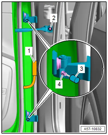
Length Adjustment
- Adjustment dimensions. Refer to → Chapter "Adjustment Dimensions".
Procedure
- Perform the preliminary work for length adjustment. Refer to → Chapter "Preliminary Work for Length and Side Adjustment".
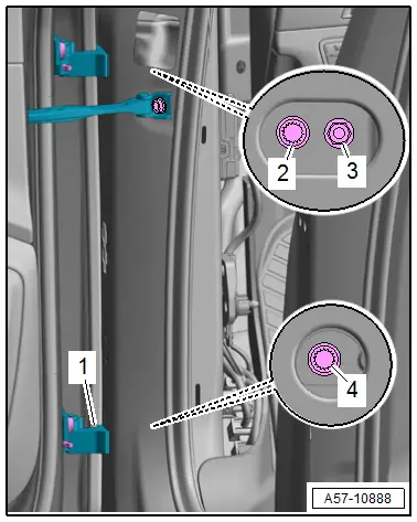
- Loosen the bolts -1, 2 and 4- and nut -3- on the hinge and on the A-pillar.
- Adjust the door lengthwise.
- Tighten the bolts and nut.
Tightening Specifications
- Refer to → Chapter "Overview - Door"
Side Adjustment
- Adjustment dimensions. Refer to → Chapter "Adjustment Dimensions".
Procedure
- Perform the preliminary work for side adjustment. Refer to → Chapter "Preliminary Work for Length and Side Adjustment".
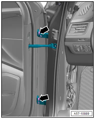
- Loosen the bolts -arrows- on the upper and lower hinge.
- Adjust the door to the center of the vehicle.
- Tighten the bolts.
Tightening Specifications
- Refer to → Chapter "Overview - Door Handle and Door Lock"
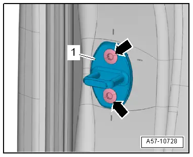
Striker, Adjusting
- Adjustment dimensions. Refer to → Chapter "Adjustment Dimensions".
Procedure
- Loosen the bolts -arrows-.
- Slide the striker -1- until the door is flush with the body contour.
- When adjusting the striker, move it only toward the center of the vehicle.
- Do not adjust the door height using the striker because the door lock will be damaged.
- When adjusted correctly, the striker must engage in the center of the door lock.
- Tighten the bolts.
Tightening Specifications
- Refer to → Chapter "Overview - Door Lock and Striker, Versions without Closing Assist"