Audi Q7: Overview - Front Level Control System Sensor
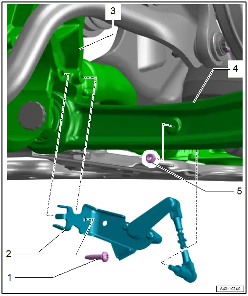
1 - Bolt
- 8 Nm
2 - Front Level Control System Sensor
- Left Front Level Control System Sensor -G78-
- Right Front Level Control Sensor -G289-
- With coupling rod and retaining plate
- Removing and installing. Refer to → Chapter "Left/Right Front Level Control System Sensor -G78-/-G289-, Removing and Installing".
- Installation position: coupling rod of the sensor points outward
3 - Subframe
4 - Control Arm
5 - Nut
- 8 Nm
- Replace after removing
- Self-locking
Overview - Rear Level Control System Sensor
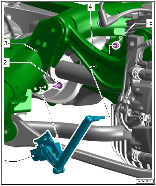
1 - Rear Level Control System Sensor
- Left Rear Level Control System Sensor -G76-
- Right Rear Level Control System Sensor -G77-
- With coupling rod and retaining plate
- Removing and installing. Refer to → Chapter "Left/Right Rear Level Control System Sensor -G76-/-G77-, Removing and Installing".
- Installation position: coupling rod of the sensor points toward the rear
2 - Bolt
- 8 Nm
3 - Subframe
4 - Transverse Link, Upper Front
5 - Nut
- 8 Nm
- Replace after removing
- Self-locking
Left/Right Front Level Control System Sensor -G78-/-G289-, Removing and Installing
Special tools and workshop equipment required
- Torque Wrench 1410 -VAG1410-
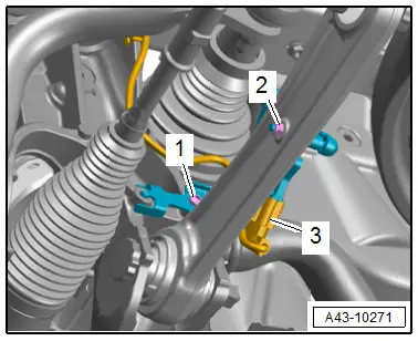
Removing
- Disconnect the connector -3- and free up the wire.
- Remove the coupling rod nut -2-.
- Remove the bolt -1- and remove the level control system sensor
Installing
Install in reverse order of removal and note the following:
Versions with Coil Springs:
- Adjust the headlamps. Refer to → Electrical Equipment; Rep. Gr.94; Headlamps; Headlamp, Adjusting.
- Driver Assistance Systems Front Camera, Calibrating. Refer to → Chapter "Driver Assistance Systems Front Camera, Calibrating".
- Infrared System, Calibrating. Refer to → Chapter "Infrared System, Calibrating".
Versions with Air Suspension:
- Readapt the standard vehicle height. Refer to → Chapter "Standard Vehicle Height, Readapting".
Tightening Specifications
- Refer to → Chapter "Overview - Front Level Control System Sensor"
Left/Right Rear Level Control System Sensor -G76-/-G77-, Removing and Installing
Special tools and workshop equipment required
- Torque Wrench 1410 -VAG1410-
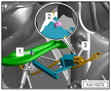
Removing
- Disconnect the connector -3-.
- Remove the coupling rod nut -1-.
- Remove the bolt -2- and remove the level control system sensor.
Installing
Install in reverse order of removal and note the following:
Versions with Coil Springs:
- Adjust the headlamps. Refer to → Electrical Equipment; Rep. Gr.94; Headlamps; Headlamp, Adjusting.
Versions with Air Suspension:
- Readapt the standard vehicle height. Refer to → Chapter "Standard Vehicle Height, Readapting".
Tightening Specifications
- Refer to → Chapter "Overview - Rear Level Control System Sensor"

