Audi Q7: Standard Vehicle Height, Readapting
The air suspension system responds automatically to changes in the vehicle level and equals these out.
The vehicle level can change in the following situations:
- Trailer Mode
- Different load conditions; vehicle empty, vehicle partially or fully loaded
For versions with air suspension system the 'level sensor end stops' and the 'level sensor zero position' must be newly adapted, when:
- A level sensor is removed and reinstalled
- A level sensor was replaced
- An air spring strut on the front axle was replaced
- An air spring on the rear axle was replaced
Requirements
- The vehicle must be standing on an even surface.
- The vehicle may not be loaded.
Procedure
- Connect the Vehicle Diagnostic Tester.
- Switch the ignition on.
- Select and start the Diagnostic operating mode.
- Select the Test plan tab.
- Select the button Individual tests and select the following tree structures one after the other:
- Suspension
- Suspension control
- 01 - OBD-capable systems
- 74 - Drivetrain Control Module J775
- 74 - Drivetrain Control Module Functions
- 74 - Complete basic setting
- Start the selected program and follow the instructions in the display of the Vehicle Diagnostic Tester.
- The standard vehicle height is reached.
If the standard vehicle height is readapted, the following work must be performed:
- Adjust the headlamps. Refer to → Electrical Equipment; Rep. Gr.94; Headlamps; Headlamp, Adjusting.
- Driver Assistance Systems Front Camera, Calibrating. Refer to → Chapter "Driver Assistance Systems Front Camera, Calibrating".
- Infrared System, Calibrating. Refer to → Chapter "Infrared System, Calibrating".
Air Suspension System, Filling and Bleeding
Bleeding
- Connect the Vehicle Diagnostic Tester.
- Switch the ignition on.
- Select and start the Diagnostic operating mode.
- Select the Test plan tab.
- Select the button Individual tests and select the following tree structures one after the other:
- Suspension
- Suspension control
- 01 - OBD-capable systems
- 74 - Drivetrain Control Module J775
- 74 - Drivetrain Control Module Functions
- 74 - Complete basic setting
- Start the selected program and follow the instructions in the display of the Vehicle Diagnostic Tester.
Filling
- To fill proceed in the same way under
- Suspension
- Suspension control
- 01 - OBD-capable systems
- 74 - Drivetrain Control Module J775
- 74 - Drivetrain Control Module Functions
- 74 - Complete basic setting
Drivetrain Control Module -J775-, Removing and Installing
Removing
- Remove the center console trim panels. Refer to → Body Interior; Rep. Gr.68; Center Console; Overview - Center Console; Overview - center console, support/cover.
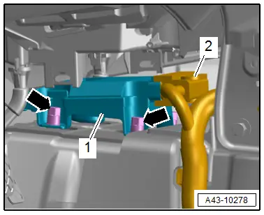
- Disconnect the connector -1-.
- Remove the left and right nuts -arrows- and remove the Drivetrain Control Module -J775-.
Installing
Install in reverse order of removal and note the following:
- After installing a new Drivetrain Control Module -J775- activate the control module.
- Connect the Vehicle Diagnostic Tester.
- Switch the ignition on.
- Select and start the Diagnostic operating mode.
- Select the Test plan tab.
- Select the button Individual tests and select the following tree structures one after the other:
- Suspension
- Suspension control
- 01 - OBD-capable systems
- 74 - Drivetrain Control Module J775
- 74 - Drivetrain Control Module Functions
- 74 - Control module, replacing
- Start the selected program and follow the instructions in the display of the Vehicle Diagnostic Tester.
- Readapt the standard vehicle height. Refer to → Chapter "Standard Vehicle Height, Readapting".
Tightening Specifications
- Refer to → Fig. " Drivetrain Control Module -J775- "
Level Control System Compressor Electronics -J1135-, Removing and Installing
Removing
- Switch off the ignition.
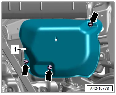
- Remove the nuts -arrows-, and remove the cover -1- for the air supply unit.
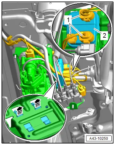
- Disconnect the connectors -1-.
- Carefully release the catches in direction of -arrows- and remove the control module -2- upward from the bracket.
Installing
Install in reverse order of removal.

