Audi Q7: Anti-Theft Alarm System
Overview - Interior Monitoring
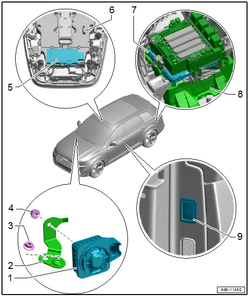
1 - Alarm Horn -H12-
- Removing and installing. Refer to → Chapter "Alarm Horn -H12-, Removing and Installing, Not for North America".
2 - Bracket
- For Alarm Horn -H12-
3 - Nut
- 3 Nm
4 - Nut
- 3 Nm
5 - Anti-Theft Alarm System Sensor -G578-
- With interior monitoring individual sensor
- Removing and installing. Refer to → Chapter "Anti-Theft Alarm System Sensor -G578-, Removing and Installing".
6 - Front Roof Module -WX3-
7 - Comfort System Central Control Module -J393-
- Removing and installing. Refer to → Body Exterior; Rep. Gr.57; Central Locking; Comfort System Central Control ModuleJ393, Removing and Installing.
8 - Bracket
- For the comfort system central control module
9 - Interior Monitoring and Vehicle Inclination Deactivation Button -E616-
- Component location overview. Refer to → Chapter "Component Location Overview - Controls in Front Doors".
Anti-Theft Alarm System Sensor -G578-, Removing and Installing
TIP
If the Anti-Theft Alarm System Sensor -G578- were replaced, it must be readapted using the Vehicle Diagnostic Tester.
Removing
- Remove the front interior lamp/reading lamp. Refer to → Chapter "Front Interior Lamp/Reading Lamp, Removing and Installing".
- Release the catches in direction of -arrows- and remove the anti-theft alarm system sensor -2- from the interior lamp/reading lamp.
- Release the retainer -3- and loosen the individual sensors -1, 4 and 5- for interior monitoring from the interior lamp/reading lamp.
- Free up the wire.
- Remove the anti-theft alarm system sensor.
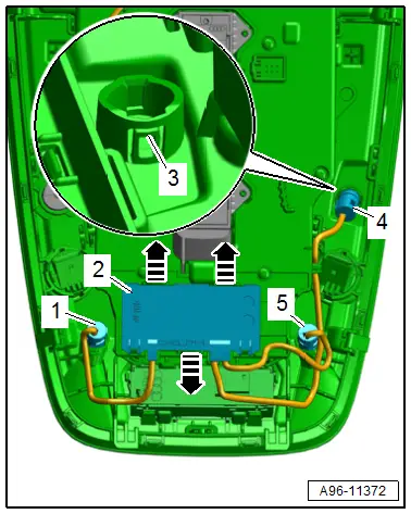
Installing
Install in reverse order of removal.

