Audi Q7: Component Location Overview - Central Locking
Audi Q7 (4M) 2016-2026 Workshop Manual / Body / Body Exterior / Front Doors, Central Locking System / Component Location Overview - Central Locking
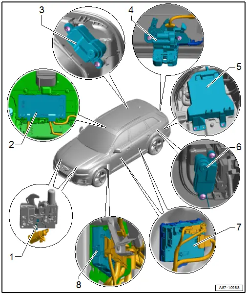
1 - Engine Hood Contact Switch
- In the latch
- Engine Hood Contact Switch -F266-
- Hood Contact Switch 2 -F329-
- Removing and Installing. Refer to → Chapter "Engine Hood Contact Switch -F266-, Removing and Installing".
2 - Anti-Theft Alarm System Sensor -G578-
- Overview. Refer to → Electrical Equipment; Rep. Gr.96; Anti-Theft Alarm System; Overview - Interior Monitoring.
3 - Fuel Filler Door Lock Motor -V155-
- Removing and Installing. Refer to → Chapter "Fuel Filler Door Lock Motor -V155-, Removing and Installing".
4 - Rear Latch
- With the Rear Lid Central Locking System Motor -V53- / Rear Lid Alarm Switch -F123-, cannot be replaced separately.
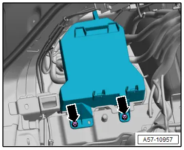
5 - Comfort System Central Control Module -J393-
- Removing and Installing. Refer to → Chapter "Comfort System Central Control Module -J393-, Removing and Installing".
- Mount tightening specifications. Refer to → Fig.
6 - High-Voltage Charge Door Lock 1 Adjuster -F496-
- Removing and Installing. Refer to → Chapter "High-Voltage Charge Door Lock 1 Adjuster -F496-, Removing and Installing".
7 - Door Control Modules
- Driver Door Control Module -J386-
- Front Passenger Door Control Module -J387-
- Door Control Module, Removing and Installing. Refer to → Chapter "Driver Door Control Module -J386- and Front Passenger Door Control Module -J387-, Removing and Installing"
- Driver Side Rear Door Control Module -J926-
- Passenger Side Rear Door Control Module -J927-
- Rear Door Control Module, Removing and Installing. Refer to → Chapter "Left Rear Door Control Module -J388- and Right Rear Door Control Module -J389-, Removing and Installing"
8 - Vehicle Electrical System Control Module -J519-
- Component Location Overview. Refer to → Electrical Equipment; Rep. Gr.97; Control Modules; Component Location Overview - Control Modules.
Tightening Specifications for Comfort System Central Control Module -J393- Mount
- Tighten nuts -arrows- to 6.5 Nm.