Audi Q7: Control Module/Digital Soand System Amplifier, Removing and Installing
Digital Soand System Control Module -J525-, Removing and Installing, BOSE
The Digital Soand System Control Module -J525- is located in the luggage compartment on the left rear.
Special tools and workshop equipment required
- Fiber-Optic Repair Set - Connector Protective Caps -VAS6223/9-.
 Note
Note
If replacing the control module, select the "Replace control module" function for the corresponding control module on the Vehicle Diagnostic Tester.
Removing
- Turn off the ignition and all electrical equipment and remove the ignition key.
- Remove the luggage compartment floor.
- Remove the left luggage compartment side trim panel. Refer to → Body Interior; Rep. Gr.70; Luggage Compartment Trim Panels; Luggage Compartment Side Trim Panel, Removing and Installing.
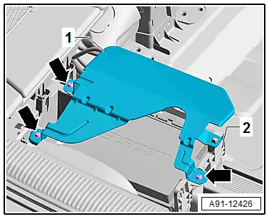
The cover must be removed first.
- Remove the bolts -arrows- on the bracket -2- and the cover -1-.
- Release and disconnect the connectors from the Digital Soand System Control Module -J525-.
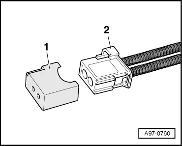
- Insert the Fiber-Optic Repair Set - Connector Protective Caps -VAS6223/9--1- onto the MOSTBusconnector -2-.

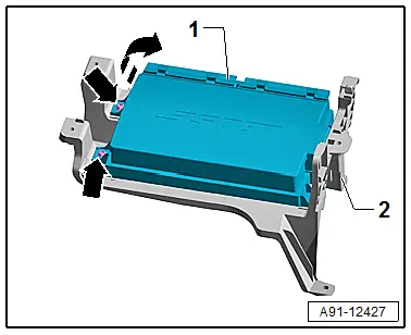
- Remove the bolts -arrows- on the bracket -2- and pivot the Digital Soand System Control Module -J525--1- in the direction of the -arrow- and remove.
Installing
- Install in reverse order of removal.
Tightening Specifications
- Refer to → Chapter "Component Location Overview - Soand System, Soand Amplifier and Microphone"
Digital Soand System Control Module -J525-, Removing and Installing, Bang & Olufsen
The Digital Soand System Control Module -J525- is located in the luggage compartment on the left rear.
Special tools and workshop equipment required
- Fiber-Optic Repair Set - Connector Protective Caps -VAS6223/9-.
 Note
Note
If replacing the control module, select the "Replace control module" function for the corresponding control module on the Vehicle Diagnostic Tester.
Removing
- Turn off the ignition and all electrical equipment and remove the ignition key.
- Remove the luggage compartment floor.
- Remove the left luggage compartment side trim panel. Refer to → Body Interior; Rep. Gr.70; Luggage Compartment Trim Panels; Luggage Compartment Side Trim Panel, Removing and Installing.
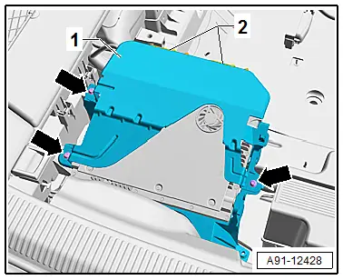
The cover must be removed first.
- Remove the bolts -arrows- on the bracket -2- and the cover -1-.
- Release and disconnect the connectors -2- from the Digital Soand System Control Module -J525-.
- Insert the Fiber-Optic Repair Set - Connector Protective Caps -VAS6223/9--1- onto the MOST Busconnector -2-.

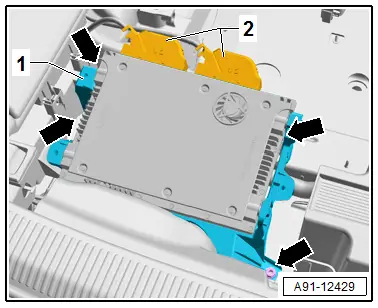
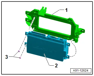
- Remove the nuts -arrows- and remove the Digital Soand System Control Module -J525- with the bracket.

- Remove the bolts -2 and 4- and remove the Digital Soand System Control Module -J525--3- from the bracket -1-.
Installing
- Install in reverse order of removal.
Tightening Specifications
- Refer to → Chapter "Component Location Overview - Soand System, Soand Amplifier and Microphone"
Digital Soand System Control Module -J525-, Removing and Installing, BOSE, e-tron
The Digital Soand System Control Module -J525- is located behind the rear seat backrest on the crossmember.
Special tools and workshop equipment required
- Fiber-Optic Repair Set - Connector Protective Caps -VAS6223/9-.
 Note
Note
If replacing the control module, select the "Replace control module" function for the corresponding control module. Refer to Vehicle Diagnostic Tester.
Removing
- Turn off the ignition and all electrical equipment and remove the ignition key.
- Fold the rear seat backrest forward.
The Digital Soand System Control Module -J525- with the bracket must first be removed.
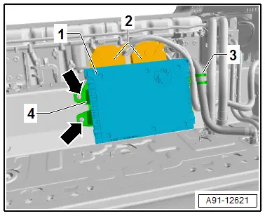
- Release and disconnect the connectors -2- from the Digital Soand System Control Module -J525--1-.
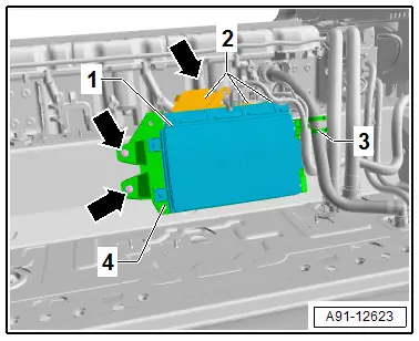
- Insert the Fiber-Optic Repair Set - Connector Protective Caps -VAS6223/9--1- onto the MOST bus connector -2-.
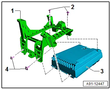
- Remove the nuts -arrows- and unclip the vent line -3- for the Hybrid Battery Unit -AX1-.
- Remove the Digital Soand System Control Module -J525--1- with the bracket -4-.

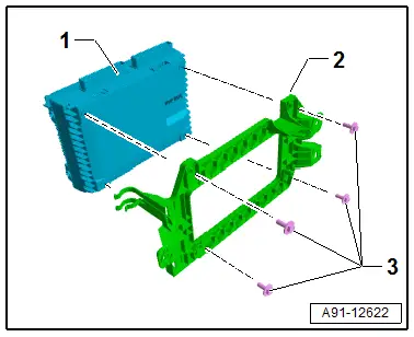
- Remove the screws -3- and pivot the Digital Soand System Control Module -J525--2- out of the bracket -1-.
Installing
- Installation is identical in reverse order of removal.
Tightening Specifications
- → Chapter "Component Location Overview - Soand System, Soand Amplifier, Subwoofer, e-tron"
Digital Soand System Control Module -J525-, Removing and Installing, Bang & Olufsen, e-tron
The Digital Soand System Control Module -J525- is located behind the rear seat backrest on the crossmember.
Special tools and workshop equipment required
- Fiber-Optic Repair Set - Connector Protective Caps -VAS6223/9-.
 Note
Note
If replacing the control module, select the "Replace control module" function for the corresponding control module. Refer to Vehicle Diagnostic Tester.
Removing
- Turn off the ignition and all electrical equipment and remove the ignition key.
- Fold the rear seat backrest forward.
The Digital Soand System Control Module -J525- with the bracket must first be removed.
- Release and disconnect the connectors -2- from the Digital Soand System Control Module -J525--1-.
- Insert the Fiber-Optic Repair Set - Connector Protective Caps -VAS6223/9--1- onto the MOST bus connector -2-.

- Remove the nuts -arrows- and unclip the vent line -3- for the Hybrid Battery Unit -AX1-.
- Remove the Digital Soand System Control Module -J525--1- with the bracket -4-.

- Remove the screws -3- and remove the Digital Soand System Control Module -J525--1- from the bracket -2-.
Installing
- Installation is identical in reverse order of removal.
Tightening Specifications
- → Chapter "Component Location Overview - Soand System, Soand Amplifier, Subwoofer, e-tron"

